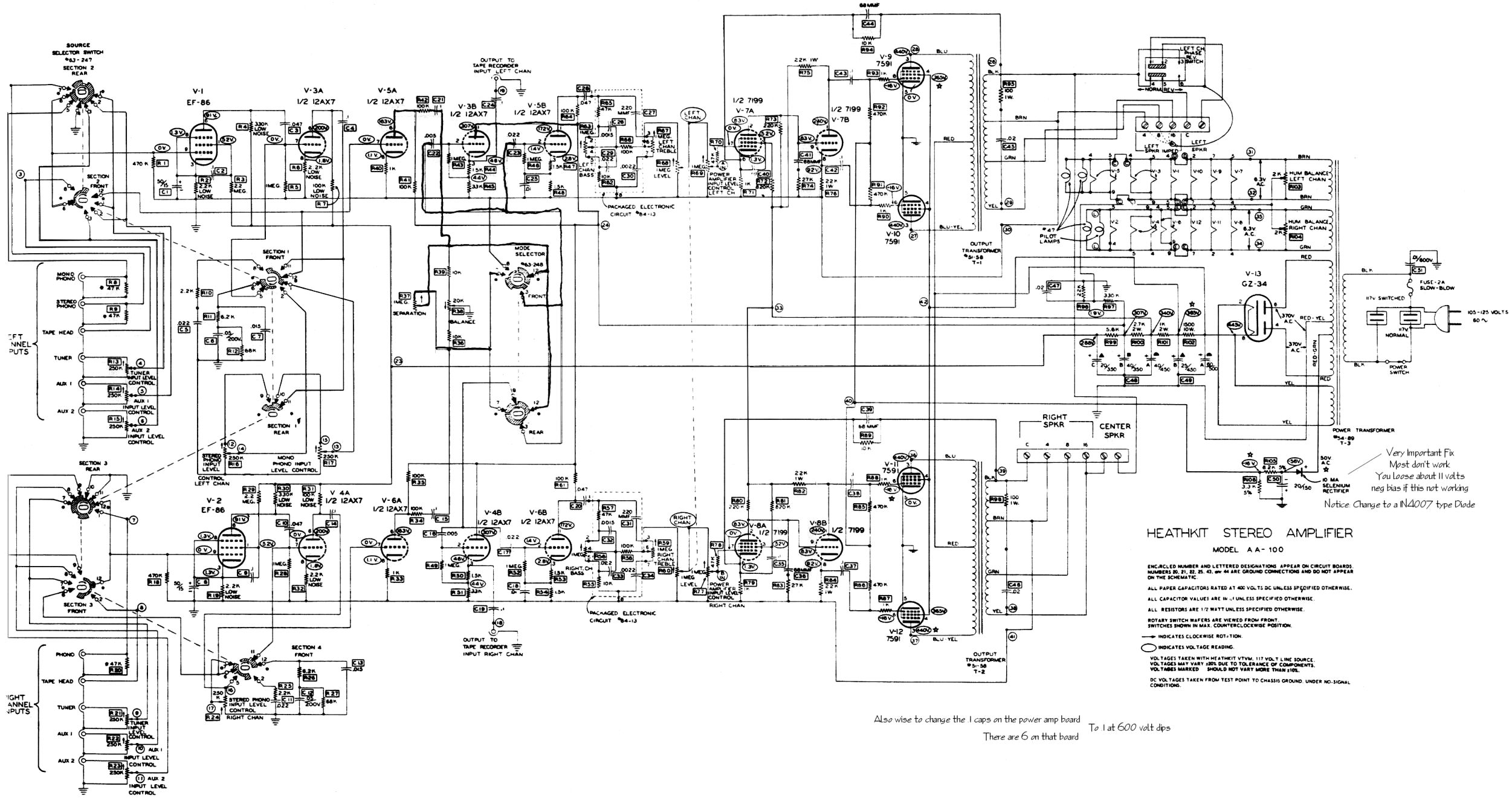
Here's a schematic of the excellent Heathkit AA-100. This amp used 7591 output tubes and the output transformers have no ultralinear taps. Looking at John Atwood's data, we can assume that the impedance matching looks pretty similar. The even higher -3dB high frequency cutoff means stability shouldn't be an issue. To use these outputs, we need to supply a screen voltage. We'll also remove and change a couple ST35 components involving the stability.
Use the current manual for reference.
Also see: http://www.diytube.com/Fender_ST35.pdf
Pentode Power Supply
We have an extra filter section that we will split into a 'Y'. One will serve the 12AX7 and 12AU7 with a target of 320V at around 3mA. The other branch will also provide around 300V or so at 20mA for the EL84 screens.
Parts Changes:
1) Change R32 to 3.3K 3W (Mouser# 72-RWM410-3K3-5).
2) Change R33 to 6.2K 2W (Mouser# 282-6.2K).
a. Cut the trace between R32 & R33. Verify with a DMM that they are separated, or even extract about 1/8" of the trace between the pads. A sharp Xacto knife works well here.
b. Using 22awg wire, solder about 1 1/2" of wire from the cut connection of R33 to the other side of R32.
c. Using 22awg wire, run a wire from the cut trace side of R32 to J5-2 as well as J2-3. For example, your R32 3W resistor could be a half inch off the PCB and you can solder your flying wires to the resistor lead.
d. Run 22awg jumper wire from J5-2 to J4-2.
e. Run 22awg jumper wire from J2-2 to J3-2.
Feedback Circuit
Parts Changes:
1) Change R1 & R2 to 12K (Mouser# 71-RN65D-F-12.1K).
2) Change C16 & C17 to 120pF (Mouser# 5982-15-500V120).
3) Omit C18, C19, C20 & C21.
4) Use the 8 ohm tap for negative feedback. Set pots R30 & R31 at 20K (you will read 21.3K from J3-3 & J4-3 to ground due to V1’s cathode resistors). Alternatively, you may use a fixed 20K resistor (Mouser# 71-RN65D-F-20K).
AA-100 Output Transformer Connections
Primary Side
-Blue/Yellow J3-1 (J4-1) [Note: I think the phase is correct, otherwise swap blue and blue/yellow if amp squeals when NFB is applied, and report back here] Yellow_Light_Colorz_PDT_05
-Blue J2-1 (J5-1)
-Red J1-3 (J1-4)
Secondary Side (assumes 8 ohm connection)
-Green to speaker terminal (with feedback taps back to J3-3 and J4-3 respectively)
-Black to speaker ground terminal and J2-3 (J5-3)
Shannon
ST35 Mod: Using the AA-100 Outputs and Pentode Configured
20 posts
• Page 1 of 2 • 1, 2
ST35 Mod: Using the AA-100 Outputs and Pentode Configured
![]() by Shannon Parks » Sun Sep 11, 2005 9:18 am
by Shannon Parks » Sun Sep 11, 2005 9:18 am
-

Shannon Parks - Site Admin
- Posts: 3764
- Joined: Tue Mar 18, 2003 5:40 pm
- Location: Poulsbo, Washington
AA100
![]() by Shannon Parks » Sun Sep 11, 2005 9:24 am
by Shannon Parks » Sun Sep 11, 2005 9:24 am
Hi Guys,
I realize I omitted the AA100 power transofrmer setup. It slipped by me. Yellow_Light_Colorz_PDT_06 Let me think about the best way to drop that extra B+ voltage. Input choke? 5U4? Dropping resistors?
Shannon
I realize I omitted the AA100 power transofrmer setup. It slipped by me. Yellow_Light_Colorz_PDT_06 Let me think about the best way to drop that extra B+ voltage. Input choke? 5U4? Dropping resistors?
Shannon
-
Shannon Parks - Site Admin
- Posts: 3764
- Joined: Tue Mar 18, 2003 5:40 pm
- Location: Poulsbo, Washington
![]() by TerrySmith » Sun Sep 11, 2005 2:30 pm
by TerrySmith » Sun Sep 11, 2005 2:30 pm
Another thing I would recommend is changing the 4 filter caps to 500v units as the 450v will puke!
Maybe try a 5R4 rectifier as it has a lot of drop.
If you could find 7189A's, they are rated at 440v on the plate. I looked at the pin-out of a 6GM5 (7591 with a 9 pin miniature base) and the EL84, and they are too different to use.
The feedback on the stock unit is backwards, and it will squeal LOUDLY!!
These are excellent transformers that often get overlooked because of no UL taps. And I don't mind parting out an AA-100 or the AA-50 (same unit, different case), as the circuit boards are usually cooked and not repairable.
Just my $.02 !
T. Smith
-

TerrySmith - KT88
- Posts: 973
- Joined: Sat Jan 31, 2004 12:51 pm
- Location: Maryville TN
more tranny choices
![]() by tubes4hifi » Thu Sep 22, 2005 11:08 pm
by tubes4hifi » Thu Sep 22, 2005 11:08 pm
the Harmon Kardon A300 outputs are also very excellent, I've used them to build several amps
-
tubes4hifi - Posts: 113
- Joined: Thu Jan 15, 2004 12:52 pm
- Location: Tacoma, WA
Re: AA100
![]() by Shannon Parks » Fri Sep 23, 2005 6:36 am
by Shannon Parks » Fri Sep 23, 2005 6:36 am
separks wrote:Hi Guys,
I realize I omitted the AA100 power transofrmer setup. It slipped by me. Yellow_Light_Colorz_PDT_06 Let me think about the best way to drop that extra B+ voltage. Input choke? 5U4? Dropping resistors?
Shannon
I decided that the AA100 output iron is definitely worth using, but it would probably be easiest to grab a PA774 from Ned or a Hammond 270HX like normal. Too many mods to tame the extra B+, though it can be done.
Thanks for the HK iron tip, Roy.
Shannon
-
Shannon Parks - Site Admin
- Posts: 3764
- Joined: Tue Mar 18, 2003 5:40 pm
- Location: Poulsbo, Washington
![]() by EWBrown » Fri Sep 23, 2005 7:47 am
by EWBrown » Fri Sep 23, 2005 7:47 am
I "parted out" an AA-100 last year, the iron was good, the rest of it was basically scrap metal (tubes not included, it was a cheapie carcass).
The power trannie is in a home built "test" power supply, the OPTs are awaiting some future project, and this one sounds like a winner for me.
Then there is the ever-increasing stack of AA-151s awaiting test/triage...
/ed B in NH
The power trannie is in a home built "test" power supply, the OPTs are awaiting some future project, and this one sounds like a winner for me.
Then there is the ever-increasing stack of AA-151s awaiting test/triage...
/ed B in NH
Real Radios Glow in the Dark
-

EWBrown - Insulator & Iron Magnate
- Posts: 6389
- Joined: Wed Mar 19, 2003 6:03 am
- Location: Now located in Clay County, NC !
![]() by TerrySmith » Wed Nov 16, 2005 5:30 am
by TerrySmith » Wed Nov 16, 2005 5:30 am
I was thinking of maybe a cap on the rectifier socket, then a resistor to feed B+ to the board, to get around 400v.
Has anyone tried a fixed bias ST35 yet?
Has anyone tried a fixed bias ST35 yet?
T. Smith
-
TerrySmith - KT88
- Posts: 973
- Joined: Sat Jan 31, 2004 12:51 pm
- Location: Maryville TN
st 35 fender mods
![]() by jbrew73 » Sun Nov 27, 2005 7:28 am
by jbrew73 » Sun Nov 27, 2005 7:28 am
could someone please explain the reasons for the mod when using the fender iron and also why it's being used with the aa-100 iron?
i'm considering a low budget build using neds fender iron or some non-u.l.
iron i pulled from an old hifi unit. just doing my homework before i start.
thanks
i'm considering a low budget build using neds fender iron or some non-u.l.
iron i pulled from an old hifi unit. just doing my homework before i start.
thanks
- jbrew73
- Posts: 9
- Joined: Sat Jun 18, 2005 3:18 pm
Re: st 35 fender mods
![]() by Shannon Parks » Sun Nov 27, 2005 12:44 pm
by Shannon Parks » Sun Nov 27, 2005 12:44 pm
jbrew73 wrote:could someone please explain the reasons for the mod when using the fender iron and also why it's being used with the aa-100 iron?
i'm considering a low budget build using neds fender iron or some non-u.l.
iron i pulled from an old hifi unit. just doing my homework before i start.
thanks
The original ST35 feedback network (eg the cap from the screens, low pass on the input) was all pretty tweaked for the iron it used, the Z565, which uses some secret voodoo winding technique. Balanced plate & cathode resistors on the 12AU7 and a more typical feedback network probably makes sense on all other iron.
You may still be able to get the Fender tranny from Triode Electronics that has the UL taps. It makes things much easier. Personally, I like the sound of a UL amp over pentode (at least for the EL84 amps). But free is always better sounding to me, too. Yellow_Light_Colorz_PDT_06
Shannon
-
Shannon Parks - Site Admin
- Posts: 3764
- Joined: Tue Mar 18, 2003 5:40 pm
- Location: Poulsbo, Washington
![]() by jbrew73 » Sun Nov 27, 2005 1:19 pm
by jbrew73 » Sun Nov 27, 2005 1:19 pm
so if using non original iron it would be best to lose the screen and input to ground caps and use balanced 27k or 33k(not one of each) resistors on the splitter?
would you make these changes for u.l. or pentode operation?
just making sure i'm clear on this.
would you make these changes for u.l. or pentode operation?
just making sure i'm clear on this.
- jbrew73
- Posts: 9
- Joined: Sat Jun 18, 2005 3:18 pm
tweaks
![]() by Shannon Parks » Wed Nov 30, 2005 8:21 am
by Shannon Parks » Wed Nov 30, 2005 8:21 am
jbrew73 wrote:so if using non original iron it would be best to lose the screen and input to ground caps and use balanced 27k or 33k(not one of each) resistors on the splitter?
Correct. Probably opt for 33k, 1W. But the larger feedback bypass cap is definitely necessary at this point - don't forget it.
jbrew73 wrote:would you make these changes for u.l. or pentode operation?
For both. Yellow_Light_Colorz_PDT_19
Shannon
-
Shannon Parks - Site Admin
- Posts: 3764
- Joined: Tue Mar 18, 2003 5:40 pm
- Location: Poulsbo, Washington
![]() by TerrySmith » Sun Dec 04, 2005 9:03 am
by TerrySmith » Sun Dec 04, 2005 9:03 am
I now have a REV C '35 up and running with AA-100 iron, sounds REALLY GOOD, but a couple of issues.
The stock power trans puts 500v on the first filter stage, so on the rectifier socket is 2 100uf @ 350v caps in series. That feeds into a 700 ohm resistor to get 390v at the first cap on the board. And that resistor gets really hot.
Is it possible to use a choke to drop appx. 110v instead of a resistor? How would I calculate the value?
The bypass resistor (20k) is a little small, at first power up it would pop and sound muddy with any loud passages. So far I added a 47K resistor to between the feedback lead and the connector.
T. Smith
-
TerrySmith - KT88
- Posts: 973
- Joined: Sat Jan 31, 2004 12:51 pm
- Location: Maryville TN
AA-100
![]() by Shannon Parks » Sun Dec 04, 2005 4:32 pm
by Shannon Parks » Sun Dec 04, 2005 4:32 pm
TerrySmith wrote:The stock power trans puts 500v on the first filter stage, so on the rectifier socket is 2 100uf @ 350v caps in series. That feeds into a 700 ohm resistor to get 390v at the first cap on the board. And that resistor gets really hot. Is it possible to use a choke to drop appx. 110v instead of a resistor? How would I calculate the value?
Hi Terry,
What rectifier are you using? Could you switch to a 5U4 type? I've used a resistor right after the rectifier but before the first filter stage. I think this will drop voltage more effectively.
As far as going with a choke input, why not download the PSU Designer program from Duncan Amps? You could twiddle away at that point. Not sure what to recommend for an input choke, though.
TerrySmith wrote:The bypass resistor (20k) is a little small, at first power up it would pop and sound muddy with any loud passages. So far I added a 47K resistor to between the feedback lead and the connector.
Is this the negative feedback you are referring to?
Shannon
-
Shannon Parks - Site Admin
- Posts: 3764
- Joined: Tue Mar 18, 2003 5:40 pm
- Location: Poulsbo, Washington
![]() by TerrySmith » Sun Dec 04, 2005 6:26 pm
by TerrySmith » Sun Dec 04, 2005 6:26 pm
I'm using two 6DW4 tv damper tubes for the rectifier, so a 5U4 or a 5R4 ain't gonna work. I have a 700 ohm 10w resistor between the rect and first stage of the board. I may get a 25w Dale aluminum resistor from Mouser.
Yes, I'm referring to the NFB circuit.
This was built on the AA-100 chassis from a previous project. I might post some pics, but it's kinda ugly!
Yes, I'm referring to the NFB circuit.
This was built on the AA-100 chassis from a previous project. I might post some pics, but it's kinda ugly!
T. Smith
-
TerrySmith - KT88
- Posts: 973
- Joined: Sat Jan 31, 2004 12:51 pm
- Location: Maryville TN
small cap
![]() by Shannon Parks » Mon Dec 05, 2005 6:38 am
by Shannon Parks » Mon Dec 05, 2005 6:38 am
TerrySmith wrote:The stock power trans puts 500v on the first filter stage, so on the rectifier socket is 2 100uf @ 350v caps in series.
Hi Terry,
I swagged your circuit in PSUII, and it looks like a 2uF or 3.3uF input cap will really drop your B+ instead of the two caps in series. Got one handy? Don't worry about the extra ripple.
Shannon
-
Shannon Parks - Site Admin
- Posts: 3764
- Joined: Tue Mar 18, 2003 5:40 pm
- Location: Poulsbo, Washington
20 posts
• Page 1 of 2 • 1, 2
Who is online
Users browsing this forum: No registered users and 37 guests