EWBrown wrote:The latest completed project is a small 6BM8...
OK... I've got just about all the chassis work on mine done. All I have to do is figure out how to finish the wiring underneath. Any hints from the expert point-to-point builders?


![]() by Ty_Bower » Sat Oct 16, 2010 5:40 pm
by Ty_Bower » Sat Oct 16, 2010 5:40 pm
EWBrown wrote:The latest completed project is a small 6BM8...

![]() by EWBrown » Sat Oct 16, 2010 6:45 pm
by EWBrown » Sat Oct 16, 2010 6:45 pm


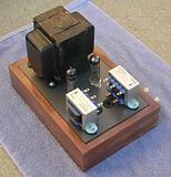
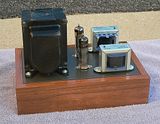
 Those trannies could easily power 8 6BM8s and maybe even 12 Your 6BM8 amp is the "Goliath" when compared to my tiny "David" version, which I can easily hold in one hand. (see it further down the page, along with a compact 12B4A "Darlikg Killer"
 .
.
![]() by Ty_Bower » Sun Oct 17, 2010 7:56 am
by Ty_Bower » Sun Oct 17, 2010 7:56 am
EWBrown wrote:I really like your nice wood bases and the nicely finished chassis plates
 I thought I'd try something different this time, rather than my usual framing lumber boxes. The first draft was a bit rougher...

![]() by EWBrown » Mon Oct 18, 2010 2:57 pm
by EWBrown » Mon Oct 18, 2010 2:57 pm

 It also took a LOT longer to warm up, and that should have been a big clue
 .
.  The 6F3P / 6BM8s consume 780 mA, so I am exceeding teh current rating by 120 mA or 4%.. Big honkin' deal...


![]() by MashBill » Mon Oct 18, 2010 5:13 pm
by MashBill » Mon Oct 18, 2010 5:13 pm
Ty_Bower wrote:EWBrown wrote:The latest completed project is a small 6BM8...
OK... I've got just about all the chassis work on mine done. All I have to do is figure out how to finish the wiring underneath. Any hints from the expert point-to-point builders?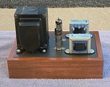

![]() by EWBrown » Tue Oct 26, 2010 9:35 am
by EWBrown » Tue Oct 26, 2010 9:35 am
I'll keep it simple, with AC filament voltage, as I've had no problems with making this operation totally hum-free.
![]() by Ty_Bower » Fri Nov 12, 2010 2:31 pm
by Ty_Bower » Fri Nov 12, 2010 2:31 pm
Ty_Bower wrote:...this schematic.
EWBrown wrote:Photos of this (and my two recent 6BM8 / 6F3P builds) coming soon...
![]() by EWBrown » Fri Nov 12, 2010 2:38 pm
by EWBrown » Fri Nov 12, 2010 2:38 pm
![]() by azazello » Sun Nov 14, 2010 1:38 pm
by azazello » Sun Nov 14, 2010 1:38 pm


![]() by EWBrown » Fri Nov 19, 2010 7:20 pm
by EWBrown » Fri Nov 19, 2010 7:20 pm
![]() by soundbrigade » Sat Nov 20, 2010 2:56 am
by soundbrigade » Sat Nov 20, 2010 2:56 am
EWBrown wrote:Nothing wrong with using paralleled or series'ed resistors where needed, I've done it more than once. I just use what I have in the junque boxes
/ed B

![]() by 20to20 » Sat Nov 20, 2010 8:30 am
by 20to20 » Sat Nov 20, 2010 8:30 am
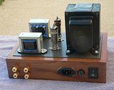
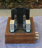
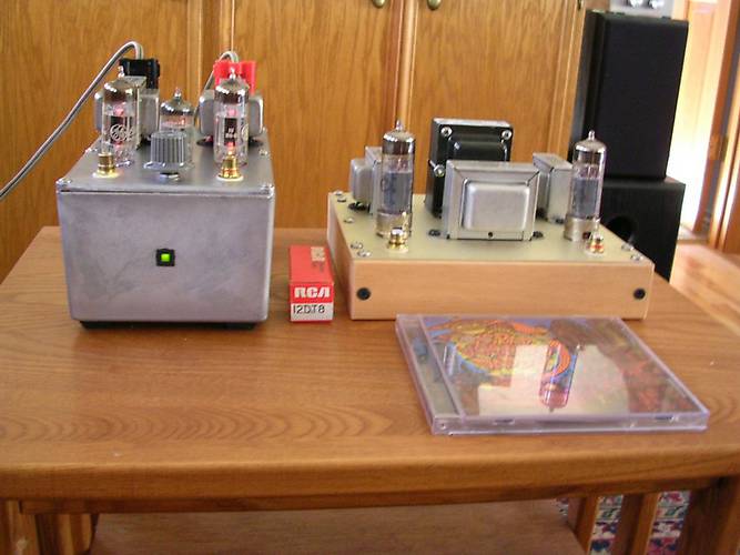
EWBrown wrote:Two more small amps, that I completed last month.
To the right, is my compact 6F3P (Russian 6BM8) SEP/UL. It measures about 6.5 X 5.5 inches and the wooden frame is 1.5 inches high. THis also uses the Triode TF103-48-UL OPTs, The circuit is that which I described in earlier postings, with two NFB paths, the usual "global" NFB from the OPT secondary to the VA cathode, and an additional plate feedback path by means of a 1 Megohm resistor connected betwen the triode and pentode plates. This addition made a dramatic difference in the sound quality, from very good to "unbelieveably excellent" for such a simple design. It is good for about 2WPC, and I did not have any room inside fir a volume control. Compare the size of the tube box and CD to the two amps. The circuit schematic for the 6F3P amp is about 2 or 3 postings above this one.
/ed B in NC

![]() by EWBrown » Sat Nov 20, 2010 6:42 pm
by EWBrown » Sat Nov 20, 2010 6:42 pm
Both in PP and SEP. , but the original pentode or triode modes sound good with these tubes . Been there, done that... ![]() by katabatic » Sun Nov 28, 2010 1:01 pm
by katabatic » Sun Nov 28, 2010 1:01 pm
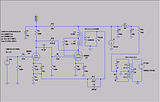
Ty_Bower wrote:Please, check this schematic Ed. I think this is what you wrote up.
I still want to see photos of your wiring.

![]() by Ty_Bower » Sun Nov 28, 2010 1:21 pm
by Ty_Bower » Sun Nov 28, 2010 1:21 pm
katabatic wrote:what is the component labeled I1, a bit above the power transformer in the schematic? The circle with the kind-of-down-arrow in it
Users browsing this forum: No registered users and 18 guests
