6DJ8 Line Stage

ask your general tube related questions here

6DJ8 Line Stage

Postby Blair » Wed Apr 01, 2009 8:46 am

I have this preamp I was working on off and on for about a year now. No real progress though. It is noisy to say the least. This last amp build gave me what I think is a much better grasp of grounding in amp circuits.

Anyway, long story short, I rerouted the grounds and the hum is much less, but not gone. One thing I am positive of, is that I should get new tubes. Not that my 6N1Ps are junk, but I think they can be subbed in for 6922s and 6DJ8s under higher voltages, but at 180v B+, I do not think they are as readily rollable. Just my theory, and maybe way off.

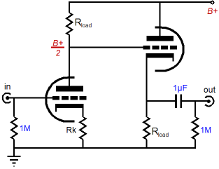
I, as stated before, am working with a fairly low B+ 175-180v. I found this schematic, and thought this would be a good starting point for a rebuild. It looks very attractive due to the low output impedance for both SS and tube amps.

Image

1) I built a regulated 6v DC filament board last night with 2,000uf filtering on it even though I'm positive there is no filament hum in the amp (I can cut the filament winding while the preamp is playing and get no change in sound).

2) I'm going to rework the PS board with a better star point system by cutting away the first filter cap after the rectifier from the rest of the ground bus and will run its own wire to the star point.

3) I added that pot on the input. Does that 1M resistor circled need to be there?

4) When you build a line stage, how do you ground your inputs/outputs? Do you ground each end of the shielded wires at all points?

5) Do you tie your cathodes together and run them as a separate return wire to the star point?

I ordered some 6DJ8 tubes yesterday, so they should be in by Friday or so. I am just not giving up on this freaking project! I believe you can make a quiet tube preamp, but I have yet to do so.

Thanks for any help!

Blair
Blair
KT88
 
Posts: 1272
Joined: Thu Nov 09, 2006 10:22 am

Postby Blair » Wed Apr 01, 2009 1:05 pm

Also,

I read somewhere that the 6922/6DJ8 like to oscillate. Can you simply add grid stopper to this design without any consequences like this?

Image

Thanks,

Blair[/url]
Blair
KT88
 
Posts: 1272
Joined: Thu Nov 09, 2006 10:22 am

Postby Geek » Wed Apr 01, 2009 6:15 pm

Hi Blair,

Values look good for a 10mA Ia to take advantage of the wicked Gm of the tube :)

What I recommend to better your noise and lower your output impedance is to use two paralleled red LED's in the cathode (Morgan Jones trick).

Example:
http://geek.scorpiorising.ca/GeeK_ZonE/ ... 1#msg46141

Cheers!
-= Gregg =-
Fine wine comes in glass bottles, not plastic sacks. Therefore the finer electrons are also found in glass bottles.
User avatar
Geek
KT88
 
Posts: 3585
Joined: Sun Oct 21, 2007 3:01 am
Location: Chilliwack, British Columbia

Postby EWBrown » Thu Apr 02, 2009 7:51 am

The 6DJ8/6922, 6N1P (and WE396A) really need the grid stoppers in order to control the spurious oscillation problem. These high gain high gm triodes will go into oscillation at the slightest excuse.

Last year I built up a VA/CF linestage with 396As, and I had a (666) of a time taming it down. The oscillation showed up as excessive "hiss" noise and the tubes were extremely microphonic.


The other necessity is to "bias" the filaments at 1/4 the B+ voltage, so that they are at a potential halfway between the two cathode voltages.

The red LED "trick" works well, and Bottlehead uses an HLMP6000 LED in the cathode of their "seduction" phono stages, which uses 6DJ8s..

/ed B
Last edited by EWBrown on Thu Apr 02, 2009 8:58 am, edited 1 time in total.
Real Radios Glow in the Dark
User avatar
EWBrown
Insulator & Iron Magnate
 
Posts: 6389
Joined: Wed Mar 19, 2003 6:03 am
Location: Now located in Clay County, NC !

Postby Blair » Thu Apr 02, 2009 8:19 am

Thanks Greg!

Should I leave in the 1K grid stoppers. I do not see them in your design.

Also, which LED configuration should I use? On one tube you have them in parallel, and the other two, they are in series.


I have wanted to try the LED bias for some time, this should be a good learning opportunity.

Thanks,

Blair
Blair
KT88
 
Posts: 1272
Joined: Thu Nov 09, 2006 10:22 am

Postby Blair » Thu Apr 02, 2009 8:31 am

EWBrown wrote:The 6DJ8/6922, 6N1P (and WE396A) really need the grid stoppers in order to control the spurious oscillation problem. These high gain high gm triodes will go into oscillation at the slightest excuse.

/ed B


Thanks Ed,

So, you would leave in the 1K grid stoppers? I wonder if that is my problem?!? The grounds look very good, and the PS is about 1/2 foot away from the tubes, and separated by a 1/8" thick piece of aluminum. I can cut the 6.3v while the preamp is playing with no change in hum at all, so I highly doubt it is the filaments.

I have 6N1P tubes in the preamp right now, but I am uncertain as to whether or not they will behave at 180v B+ vs the 6DJ8 which you see commonly used at B+ 180v.

It is a bear having these big monoblocks running and knowing they are quiet, and then I hook up the preamp and they sound like a kiss concert before the opening act :(

Thanks,

Blair
Blair
KT88
 
Posts: 1272
Joined: Thu Nov 09, 2006 10:22 am

Postby Blair » Thu Apr 02, 2009 8:32 am

Also,

Do they have to be red LEDs? I'm partial to other colors (???)

Blair
Blair
KT88
 
Posts: 1272
Joined: Thu Nov 09, 2006 10:22 am

Red is for 6DJ8s and sometimes 12AU7s)

Postby EWBrown » Thu Apr 02, 2009 9:08 am

The reason for the LED color is the forward voltage, and red LEDs are generally 1.6 to 1.8VDC, and the HLMP600s are unique in that htey run at a slightly lower voltage, and their consistency from batch to batch is quite precise, all that I've measured fall between 1.56 and 1.57 volts with 3.5 to 4 mA current. These LEDs will never win any brightness contests, as they are very dim, but in this cathode biasing application, the foreward voltage drop is the key factor.

For most applications, any cheap red LED will serve very well. For some applications requiring higher bias voltages the LEDs can be connected in series, as required.

The modern "true" green, blue, and white LEDS run between 3.6 and 4 VDC, yellow LEDs are generally between 1.8 and 2V, and the old "slime green" ones are between 2 and 2.2 VDC.

I've not tried them in a tube circuit, but IR LEDs are around 0.9 and 1.2V which may come in handy for th lower bias voltage situations.

I would not use UV, violet or pink (phosphor) LEDs as they generally have a fairly short operating lifetime.

Needless to say, never use the multicolor or flasher LEDs as they have a constantly varying forward voltage drop., and will generate lots of unwanted noise and other circuit nuisances.

I did see over at the tubelab.com site that George was experimenting with series-connected higher current white LEDs as the cathode loads for a small EL84 PP amp that he is designing. In his application, he wanted around 11VDC and 40 mA cathode bias, and three of these LEDs in series worked very nicely, and produced lots of white light in the process.


You can always throw in some extra colorful LEDs just for effect, as long as they are not part of the acttive circuit.

(lol)

IIRC you had earlier asked about the 1 meg resistor between the volume control and tube. It isn't absolutely necessary, but it is a good safety device in case the pot's wiper becomes intermittent, as it will keep the input tube's grid at zero volts potential, and prevent current "runaway" situations. Like the "safety resistors" on the Big Amp's bias adjustment pots.


/ed B
Last edited by EWBrown on Thu Apr 02, 2009 9:15 am, edited 1 time in total.
Real Radios Glow in the Dark
User avatar
EWBrown
Insulator & Iron Magnate
 
Posts: 6389
Joined: Wed Mar 19, 2003 6:03 am
Location: Now located in Clay County, NC !

Postby Blair » Thu Apr 02, 2009 9:13 am

Thanks Ed!

I suppose it is off to the surplus shop today during lunch. I should get my 6DJ8 tubes today vs. the 6N1Ps. Now, I just need something to do with 8 6N1Ps???

In the schematic Greg referenced, he is using a single point to tie all the stages together an running a single ground. Is this OK in a preamp design? The cathodes can be grounded with the rest of the circuit i.e. the input and output, pin 9 etc.?

Also, is there a need to decouple the pin 9 connection via a cap/resistor, or will a short wire suffice?

Thanks,

Blair
Blair
KT88
 
Posts: 1272
Joined: Thu Nov 09, 2006 10:22 am

Postby EWBrown » Thu Apr 02, 2009 9:18 am

In a linestage or other higher gain preamp, circuit grounding is the crucial factor, and any good "Star" grounding scheme will work best, with only a single point connection to the chassis. The "star" ground can be run into a ground buss, it doesn't ncessarily have to be a literal "star" with alll ground points coming together at a single nexus.

I like using the isolated RCA connectors, this prevents ground loops and the nasty noise and hummmm situations.

In my own designs, I prefer to use lower mu tubes (6SN7, 12AU7, 6CG7, 12BH7, 6350, etc) for line stages, as they generally only need to have a voltage gain of 6 to 10. With higher mu tubes, comes more noise, instability, oscillations, etc. One very easy way to reduce the gain, and noise, is to remove the (lower tube) cathode bypass cap.

My own preferred use for 6DJ8 and 6N1P, and other similar triodes, is for VA drivers in small EL84 or 6S4A SE amps, where the higher gain of 12AX7, 6SL7 or 5751 is not required. They work well in either grounded cathode or symmetrical SRPP (like your circuit).

For a good tutorial on basic line stage construction and good techniques, check out this site:

http://wardsweb.org/audio/foreplay.html

Luther Ward walsk us through every step of building a Bottlehead "Foreplay II" linestage, which is a very simple direct-coupled VA/CF design, which provides excellent performance. THe wiring and grounding scheme is applicable to any linesage project, whether VA/FC, SRPP or grounded cathode.

The Foreplay II's basic VA/CF circuit is very similar to this one on Gary Kaufman's wenbsite, just use a 12AU7, 6CG7 or 6SN7 in place of the WE407A. The Foreplay B+ is around 160VDC, similar to your circuit.

It is pretty easy to "reverse engineer" the schematic, but here is a near equivalent:

Firstly, from John Broskie's website:

Image

This is the basic "bare bones" VA/CF circcut, less component values.

Next, from Gary Kaufman:

http://www.the-planet.org/images/407a.jpg


Image

In both examples, the filaments should be referenced to approx 1/4 of the B+ voltage, as with the SRPP design.

This is also the circuit that I "borrowed" for my previously mentioned WE396A linestage. In this case, the B+ is around 215VDC, but with the other tubes,

A B+ voltage of 160-165VDC is near perfect with the given 22K resistor values. These will run around 3.5 mA current for each section, and the 22K plate and cathode resistors should be 1 watt. The VA cathode resistor can be a common cheap red LED, instead of the 1K cathode resistor.

The HLMP6000 is ideal for this, but any common red LED will work quite nicely. The goal is to have around 1.6 V on the VA's cathode. The cathode resistor can be 430 ohms, inetead of the LED.

/ed B
Last edited by EWBrown on Thu Apr 02, 2009 12:34 pm, edited 3 times in total.
Real Radios Glow in the Dark
User avatar
EWBrown
Insulator & Iron Magnate
 
Posts: 6389
Joined: Wed Mar 19, 2003 6:03 am
Location: Now located in Clay County, NC !

Postby Blair » Thu Apr 02, 2009 9:39 am

Do you have a good schematic of a 6CG7 amp using a low B+ voltage like 160-80v?

I still have those 6CG7s I purchased for my big tube amps prior to having to move the tubes over for space issues. I'm glad I did though. It may have saved me in the long run! ;)

I think this will be interesting, I have this chassis and if I purchase a few PCB protoboards, I can build several circuits that can be plugged in for the B+ and filament voltage. Could be kind of fun. What would be even more fun would be to place a multi pole switch that switched between each type of tube something like a 4 pole 3 position switch. Now I'm getting out there. Must be time for another cup of coffee!! (lol)

If you do manage to come across a schematic for a good 6CG7 line stage using a lower B+, I'd like to see it.

Thanks,

Blair
Blair
KT88
 
Posts: 1272
Joined: Thu Nov 09, 2006 10:22 am

Postby EWBrown » Thu Apr 02, 2009 10:06 am

I updated the previous posting to include the relevant information.

If you make up some proto boards, then it should be relatively easy to run off some VA/CF boards and some basic SRPP boards, then experimenting and Tube-CAD will be your "best friend" for determining the resistor values.

It is simple enough to make them 9A and 9AJ base compatible, this covers all teh standard preamp tubes like 12AU7, 6CG7, 6N1P, etc. The only difference being pin 9, which is filament center tap for 12AU7s and an internal shield for 6CG7s and 6N1Ps.

Note that the 407A, 396A, 2C51 and 5670 all have a dofferent "non-standard" pinout which is not compatible with either of the 9A or 9AJ basing.


HTH

/ed B
Real Radios Glow in the Dark
User avatar
EWBrown
Insulator & Iron Magnate
 
Posts: 6389
Joined: Wed Mar 19, 2003 6:03 am
Location: Now located in Clay County, NC !

Postby Blair » Thu Apr 02, 2009 12:52 pm

Very good information Ed!

I got some red LEDs during lunch, so I'll give this a try. I also bought a protoboard so I can give it a try building a "plug n
play" board. If it all works well, I'll build a few protoboards with a few 12AU7s, 6CG7s, and maybe even a 5670 (They are dirt cheap!)

As long as the preamp gets quiet I could care less what tubes are used! You would think it would be dang near impossible to mess up grounds when the filaments are DC, the B+ is DC and the entire tube circuit ground to a single bus with a single wire to the star point. (???) I use insulated RCAs as well.

Thanks,

Blair
Blair
KT88
 
Posts: 1272
Joined: Thu Nov 09, 2006 10:22 am

Postby EWBrown » Thu Apr 02, 2009 12:59 pm

The nice part about using a PC board is that you will have a self-contained ground buss already, and that eliminates most of the hummmmm and spurious noise problems. Itis easy then to have a single connection for PC ground to chassis ground.

/ed B (time for me to go home!)
Real Radios Glow in the Dark
User avatar
EWBrown
Insulator & Iron Magnate
 
Posts: 6389
Joined: Wed Mar 19, 2003 6:03 am
Location: Now located in Clay County, NC !

Postby Geek » Thu Apr 02, 2009 5:00 pm

Wow, a lot happened here overnight :))

The grid stoppers can't be over emphasized. I just used 330R because I have a few hundred on hand. 1K is OK too. It's not that critical as to value.... just enough for the R and Cmiller to make a LPF to kill any parasitic oscillating tendencies.

If you don't provide an ECC88 with RF, they will make their own... - Allen Wright (6DJ8 preamp guru)


<plug>
If anyone wants to play with that "Bare Bones" VA/CF, I have PCB's ;)
</plug>

Cheers!
-= Gregg =-
Fine wine comes in glass bottles, not plastic sacks. Therefore the finer electrons are also found in glass bottles.
User avatar
Geek
KT88
 
Posts: 3585
Joined: Sun Oct 21, 2007 3:01 am
Location: Chilliwack, British Columbia

Next

Return to tube 101

Who is online

Users browsing this forum: No registered users and 12 guests

cron