I read this article Ty pointed me to about op points for single ended applications and I believe this applies to the Aikido.
It seems straight forward, you need the B+ (about 255v in my case) and plate resistance to get you started. I will be using 6n1p and 6n6p to start, but I want to swap out other tubes later.
What is the plate resistance used in the Aikido?
I do have a second question, is the R15 value calculated with the MU of the output tube?
Thanks, Zap.
Could use some help with Tube Operating points for Aikido.
8 posts
• Page 1 of 1
Could use some help with Tube Operating points for Aikido.
![]() by CpuZapper » Mon Mar 16, 2009 11:18 am
by CpuZapper » Mon Mar 16, 2009 11:18 am
-
CpuZapper - Posts: 116
- Joined: Tue Jul 03, 2007 7:35 pm
- Location: Alberta, Canada
![]() by EWBrown » Mon Mar 16, 2009 11:58 am
by EWBrown » Mon Mar 16, 2009 11:58 am
The AIkido is basically a fancy SRPP design, so the resistors of interest would be the tubes' cathode resistors, as there are no plate resistors per se.
The Aikido 9 pin stereo PCB instructions are here:
http://www.tubecad.com/Nine-Pin_Aikido_PCB.pdf
THis board works with just about any 9A or 9AJ based tube.
R15 is dependent on the output tube's mu (gain factor). I know for 6CG7, it is 82.5K, for 6N6P it should be around 83.33K the formula for R15 is R16 (100K) X (mu -2)/(mu+2)
6N6P, the mu is 22, so that works out to 100K X (20/24) or 83.33K
6N6P data:
http://frank.pocnet.net/sheets/113/6/6N6P.pdf
It is similar to, but not exactly, ECC99.
There is a chart which covers several tubes and the ideal resistor values, and it does cover 6N1P, though not the 6N6P..
For the 6N1P, with a 250V B+, running at 5 mA, RK (R2 and R4) should be 220 ohms. This gives the input stage a gain of 17.7. The output always has a gain around 0.9, so expect a total gain around 16.
As far as the cathode resistors (R8, R11) for the 6N6P, I'll have to run a simulation with tube cad:
This is only an approximation, as "added" tube data doesn't always work out perfectly with tube cad:
Given that B+ is 255V, and using the 6N6P "plugged in" data I get:
RK is R8 and R11 for the output tube, (and R2 and R4 for the input tube).
for 10.5 mA, RK should be 470 ohms
For 10 mA, RK should be 500 ohms
For 7.7 mA, RK should be 680 ohms,
For 5.4 mA, RK should be 1000 0hms.
I chose to use standard resistor values, hence the odd current values.
The chart in the 9 pin Aikido data contains the 6N1P resistor alues.
It's best to use 1% metal films here, to keep things closely balanced.
FWIW, I'm in the process of assembling one of the new Aikido "All-in-one" boards as a VA / CF for a future SET project. THe input tubes will be 12AX7s, the output 6CG7s. Includes power supplies for both B+ and regulated DC filaments.
There were a few missing resistors, and John is sending them today, so I'll be ableto complete the board soon.
Looks like this:
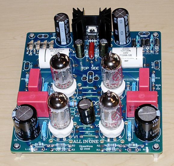
Update 3/19/09:
John not only sent me the few missing resistors, he sent the whole "suite" of resistors for another board! Now, THAT's great customer service !!! Yellow_Light_Colorz_PDT_06
/ed B
The Aikido 9 pin stereo PCB instructions are here:
http://www.tubecad.com/Nine-Pin_Aikido_PCB.pdf
THis board works with just about any 9A or 9AJ based tube.
R15 is dependent on the output tube's mu (gain factor). I know for 6CG7, it is 82.5K, for 6N6P it should be around 83.33K the formula for R15 is R16 (100K) X (mu -2)/(mu+2)
6N6P, the mu is 22, so that works out to 100K X (20/24) or 83.33K
6N6P data:
http://frank.pocnet.net/sheets/113/6/6N6P.pdf
It is similar to, but not exactly, ECC99.
There is a chart which covers several tubes and the ideal resistor values, and it does cover 6N1P, though not the 6N6P..
For the 6N1P, with a 250V B+, running at 5 mA, RK (R2 and R4) should be 220 ohms. This gives the input stage a gain of 17.7. The output always has a gain around 0.9, so expect a total gain around 16.
As far as the cathode resistors (R8, R11) for the 6N6P, I'll have to run a simulation with tube cad:
This is only an approximation, as "added" tube data doesn't always work out perfectly with tube cad:
Given that B+ is 255V, and using the 6N6P "plugged in" data I get:
RK is R8 and R11 for the output tube, (and R2 and R4 for the input tube).
for 10.5 mA, RK should be 470 ohms
For 10 mA, RK should be 500 ohms
For 7.7 mA, RK should be 680 ohms,
For 5.4 mA, RK should be 1000 0hms.
I chose to use standard resistor values, hence the odd current values.
The chart in the 9 pin Aikido data contains the 6N1P resistor alues.
It's best to use 1% metal films here, to keep things closely balanced.
FWIW, I'm in the process of assembling one of the new Aikido "All-in-one" boards as a VA / CF for a future SET project. THe input tubes will be 12AX7s, the output 6CG7s. Includes power supplies for both B+ and regulated DC filaments.
There were a few missing resistors, and John is sending them today, so I'll be ableto complete the board soon.
Looks like this:
Update 3/19/09:
John not only sent me the few missing resistors, he sent the whole "suite" of resistors for another board! Now, THAT's great customer service !!! Yellow_Light_Colorz_PDT_06
/ed B
Last edited by EWBrown on Thu Mar 19, 2009 3:07 pm, edited 1 time in total.
Real Radios Glow in the Dark
-

EWBrown - Insulator & Iron Magnate
- Posts: 6389
- Joined: Wed Mar 19, 2003 6:03 am
- Location: Now located in Clay County, NC !
![]() by CpuZapper » Mon Mar 16, 2009 1:43 pm
by CpuZapper » Mon Mar 16, 2009 1:43 pm
Hi Ed, thanks for the help.
I want to try tubes or b+ ranges not listed in the manual so I was hoping to learn how to make that educated guess. I was using the Russian tubes as examples one I could double check with the manual (6n1p).
I read the plate resistance is controlled by the voltage divider in the Aikido but I don't know if this is valid?
What should I use as a estimated value for rough calculations?
If you calculate the RK for 6n1p in tube cad at 220 ohms what did it show as the plate resistance?
What are normal standards 10k or 100k?
For the 6n6p I have read don't run it under 16ma, what is 220 Ohm for the 6n6p in tube cad, should be about 16-18ma?
I just finished the stand alone power supply from Glassware Audio.
Have to order some resistors and get this Aikido running.
-
CpuZapper - Posts: 116
- Joined: Tue Jul 03, 2007 7:35 pm
- Location: Alberta, Canada
![]() by TerrySmith » Mon Mar 16, 2009 1:47 pm
by TerrySmith » Mon Mar 16, 2009 1:47 pm
I've ended up with 5751 on the input side and 5814A on the output side of my Aikido. I like the higher gain in the input section. Since I redid the power supply I can only run 12v tubes.
T. Smith
-

TerrySmith - KT88
- Posts: 973
- Joined: Sat Jan 31, 2004 12:51 pm
- Location: Maryville TN
![]() by mesherm » Mon Mar 16, 2009 2:17 pm
by mesherm » Mon Mar 16, 2009 2:17 pm
Crap...I wished JB had had those All-in-ones available when I built my 2A3 and 300B amps. I used the older 9 pin and 8 pins versions as drivers and they worked great although they took up a lot of room inside the chassis. Now I'm going to have to buy a couple of these new PCBs and see if they will drive the 811a SE amp I am planning.
Mike's N-1 Rule: When looking for N number of components to finish a job, you have a 95% chance of only finding N-1 of them.
-

mesherm - KT88
- Posts: 1232
- Joined: Fri Aug 27, 2004 10:33 pm
- Location: Alvin Texas
![]() by EWBrown » Tue Mar 17, 2009 6:32 am
by EWBrown » Tue Mar 17, 2009 6:32 am
The "all in ones" are brand new, I have one of the first units he sold.
The board is 6 inches wide, 6 1/2 inches front to back. The heatsink and LD1085 regulator (as well as the tube sockets) have to mount on top, the resistors, capacitors, rectifiers and other small parts can mount on either side
So it could be a bit problematical to mount it under the chassis in the normal nammer...
I'm interesting in the pending stereo aikido PP driver board, that could be cool Yellow_Light_Colorz_PDT_06
/ed B
Real Radios Glow in the Dark
-
EWBrown - Insulator & Iron Magnate
- Posts: 6389
- Joined: Wed Mar 19, 2003 6:03 am
- Location: Now located in Clay County, NC !
![]() by EWBrown » Thu Mar 19, 2009 3:11 pm
by EWBrown » Thu Mar 19, 2009 3:11 pm
The Aikido doesn't use plate resistors, only the two cathode resistors per SRPP stage. The output section is a modified symmetrical SRPP acting as a cathode follower, and the calculations for rk vs current still apply as if it were a normal symmetrical SRPP.
The "plate resistance" indicated in the tube / voltage chart is the tubes internal P to K resistance, AKA rP.
A tube's rP, and gm (transconconductance) will vary with different plate voltages and currents, but the mu (amplification factor) remains fairly constant.
HTH
/ed B
The "plate resistance" indicated in the tube / voltage chart is the tubes internal P to K resistance, AKA rP.
A tube's rP, and gm (transconconductance) will vary with different plate voltages and currents, but the mu (amplification factor) remains fairly constant.
HTH
/ed B
Real Radios Glow in the Dark
-
EWBrown - Insulator & Iron Magnate
- Posts: 6389
- Joined: Wed Mar 19, 2003 6:03 am
- Location: Now located in Clay County, NC !
![]() by CpuZapper » Wed Mar 25, 2009 1:05 pm
by CpuZapper » Wed Mar 25, 2009 1:05 pm
JB replied to an email, by the way he has been very good at answering my emails, I hate to ask so many questions but I do want to learn more about this.
Some Theory.
http://www.tubecad.com/articles_2003/Gr ... lifier.pdf
Iq = B+/2(rp + [mu + 1]Rk)
For example, a 12AX7 in an Aikido circuit with a B+ voltage of +300V and 1k cathode resistors will draw
300/2(60k + [100 + 1]1k) amperes of current, or 0.93mA.
More info about this formula can be found in the Aikido PH-1 doc.
http://www.tubecad.com/2008/07/13/PH-1% ... preamp.pdf
I still have to read this info myself.
-
CpuZapper - Posts: 116
- Joined: Tue Jul 03, 2007 7:35 pm
- Location: Alberta, Canada
8 posts
• Page 1 of 1
Who is online
Users browsing this forum: No registered users and 4 guests