The original Dynaco Mk3 has a shared bias circuit for the tube pair. Shannon's design improves upon this with an additional multi-turn trim pot located on the Poseidon board. This allows you to individually set the bias for each output tube. In order that you can measure each tube's idle current, separate cathode sense resistors must be installed.
1/4 watt is plenty. Each tube should draw 70 mA at idle. Across a 10 ohm resistor, you will see a 0.7 volt drop (V=I*R). Power dissipated in the resistor will be only 0.05 watt (P=I*V). If my math is right, the maximum current through the tube should be no more than 186 mA during impossibly loud peaks. Even at that current you'll only burn 0.35 watt in the cathode resistor.
The idea behind the cathode resistors' size is that it will act as a fusible link. If you are continuously running more than 1/4 watt through that resistor, something has gone wrong. Hopefully the resistor will burn out before your expensive output transformer does.
I couldn't say if the screen ballast resistor is necessary. Obviously, Dynaco felt it wasn't required. Then again, I disagree with several of their other design decisions, such as the usage of 525 volt rated power supply capacitors. Many people suggest the screen resistor is a prudent addition, which could potentially extend the life of the output tubes. I have only read one negative remark concerning the screen resistor; it suggested the amp sounded better without it. If I can find the article that promotes the concept, I'll post it here.
Edit - Here it is: http://www.audioxpress.com/magsdirx/ax/ ... ie2544.pdf
Look at the part starting on page 3 under the heading "Simple Solution".
Forgot to answer your first question. My P782 makes just under 900VCT with no load. If you've got a solid state plug in rectifier which you intend to use, the DC rail coming off the rectifier could be as much as sqrt(2)*900/2, or 635 volts.
Good thing I don't build these for a living...
64 posts
• Page 1 of 5 • 1, 2, 3, 4, 5


![]() by FATMAN » Sat Nov 01, 2008 1:43 am
by FATMAN » Sat Nov 01, 2008 1:43 am
Ty thanks for the information I guess the hamond choke will be underated at only 400 volts, I phoned about my order at triodelectronics and my chokes are finally on the way so I can go further on finishing mine when they come. I think they should be here buy next week end. thanks for your help hopfuly i wired it up right and it will work. Your amps look nice with original tranny's. Next project I have a harmon Kardon citation 1 to recap next for my preamp. Cheers Andrew
- FATMAN
- Posts: 36
- Joined: Sat Sep 30, 2006 9:12 am
- Location: Waterloo Ontario
![]() by Ty_Bower » Sat Nov 01, 2008 6:07 am
by Ty_Bower » Sat Nov 01, 2008 6:07 am
Yes, the Hammond's working voltage rating seems low. Too low, when you consider the construction appears identical to other units with voltage ratings in the kV.
I don't know why it didn't occur to me sooner - I bet the Triad C-24X would be a fine drop-in replacement for the C354.
http://www.alliedelec.com/Images/Produc ... /C-24X.PDF
I don't know why it didn't occur to me sooner - I bet the Triad C-24X would be a fine drop-in replacement for the C354.
http://www.alliedelec.com/Images/Produc ... /C-24X.PDF
-

Ty_Bower - KT88
- Posts: 1494
- Joined: Wed Mar 21, 2007 2:50 pm
- Location: Newark, DE
![]() by Ty_Bower » Sat Nov 01, 2008 2:23 pm
by Ty_Bower » Sat Nov 01, 2008 2:23 pm
It's about time. How long ago did I start this project?
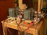
It's not really happy with the cheapo 6L6 tubes. I had to crank the bias pots all the way counterclockwise to keep away the red plates. Idle current is about 40 mA per tube. I shudder to think what the B+ must be like with such a light load on the power supply. It's a good thing the SDS board is rated up to 630VDC. J & K are both about 50 volts higher than they should be. Seeing as how nothing has blown up, I'll probably put the good tubes in later tonight.
Special thanks to Dave, who finally inspired me to get off my duff and finish these things.
-
Ty_Bower - KT88
- Posts: 1494
- Joined: Wed Mar 21, 2007 2:50 pm
- Location: Newark, DE
![]() by TomMcNally » Sat Nov 01, 2008 3:26 pm
by TomMcNally » Sat Nov 01, 2008 3:26 pm
Nice job Ty ! There is a simple resistor mod in the Dynaco
manual to get more bias voltage for tubes that need it.
The only thing I would have done differently would be to
mount the board components on the bottom, to keep
them away from the heat of the tubes.
Those amps will rock the house - they are sweet !
manual to get more bias voltage for tubes that need it.
The only thing I would have done differently would be to
mount the board components on the bottom, to keep
them away from the heat of the tubes.
Those amps will rock the house - they are sweet !
-

TomMcNally - Darling du Jour
- Posts: 2729
- Joined: Sat Nov 19, 2005 2:19 pm
- Location: Northfield, NJ
![]() by Ty_Bower » Sat Nov 01, 2008 7:03 pm
by Ty_Bower » Sat Nov 01, 2008 7:03 pm
They're coming along very nicely. Those horns are going to be loud. I can't remember if you mentioned it earlier, but that's definitely an Uncle Ned kit if I ever saw one.
I bet you can't wait to get those chokes. Probably should have put in the bolts for them. It's going to be tricky to get the bolts in underneath the power transformer with all the leads attached.
I can't decide if you have your SDS board turned around 180 degrees, or maybe I do. It looks like the end of your bias supply filter cap (the Sprague Atom) is flying. I'd tie that down to something. The last thing you want is for the bias supply to short out against the chassis bottom while the amp is running. By the way, where's the red/black bias tap going? It looks like it's landed on the SDS board. Did you leave the diodes on the board? I guess there's no reason not to mount the bias rectifier there, but be sure to cut the trace on the circuit board to separate the bias rectifier from the rest of the high voltage filter circuit.
Curious method of mounting the 1K grid stopper resistors. Not exactly textbook, but I suppose it should work.
Generally, the AC wiring is twisted together to minimize leaked hum. That would mostly be the 6.3V and 5.0V heater wiring and the high voltage secondary leading to the rectifier tube socket. Most people also twist the leads to the C354 filter choke as well.
-
Ty_Bower - KT88
- Posts: 1494
- Joined: Wed Mar 21, 2007 2:50 pm
- Location: Newark, DE
![]() by Ty_Bower » Sat Nov 01, 2008 7:11 pm
by Ty_Bower » Sat Nov 01, 2008 7:11 pm
I nearly missed it the first couple times I looked at your photo... the kit included a 600V mylar film cap to go between the heater center tap (green/yellow) and ground? Interesting. I guess that's the way it's done these days. In the 60's Dynaco used a ceramic disc capacitor there. That's what I put in mine too. But, I do have another amplifier with a more modern design. The designer recommended a film cap be used at a similar location in the circuit. I wonder if there is any technical reason why one is better than the other.
-
Ty_Bower - KT88
- Posts: 1494
- Joined: Wed Mar 21, 2007 2:50 pm
- Location: Newark, DE
![]() by FATMAN » Sun Nov 02, 2008 5:34 am
by FATMAN » Sun Nov 02, 2008 5:34 am
The pictures were from the first day, I have changed the flying conection and installed a 4 way terminal lug to hold the conection with the red black tranformer tap to the diode,( moved it from the corner of the cap board) I will need to lift the Transformer to put the screws to hold the chokes, I will learn these little things before I start the second one. I wonderd about the milar film cap too,I was not sure it was the right spot for it,but it measured .02mf so I used it there. It came in the bias control kit they sent. (Who is Uncle Ned?) Yes the horns can go very loud but that's not the main objective, the larger the horn the smoother and more full the sound is, the lower you can play them and still have a very full rich bass,even at the lowest levels. Yes can't wait for the chokes now that they are so close! it has been over 2 years for me to finally get this far with the dynaco's. It should be a lovely new pair of vintage MK3's, Glad there are those who keep them alive and better than ever.
- FATMAN
- Posts: 36
- Joined: Sat Sep 30, 2006 9:12 am
- Location: Waterloo Ontario
![]() by Ty_Bower » Sun Nov 02, 2008 5:47 am
by Ty_Bower » Sun Nov 02, 2008 5:47 am
Uncle Ned was once affiliated with Triode Electronics. He has since parted ways with the rest of the owners of the shop. For a short while I think he spent some time in Europe, but I wouldn't swear to it. His 'net presence doesn't seem to be as prominent as it once was. Do a Google Groups search through the old rec.audio.tubes archives and you'll find many posts by him.
He still runs a store at TubeZone.net. It's actually a portal to an eBay storefront. His Poseidon kits are distinctive in that they include the staked terminal connectors, Wima box caps, and often used carbon composition resistors in the signal path. I bought my Poseidon board kits from him last year.
He still runs a store at TubeZone.net. It's actually a portal to an eBay storefront. His Poseidon kits are distinctive in that they include the staked terminal connectors, Wima box caps, and often used carbon composition resistors in the signal path. I bought my Poseidon board kits from him last year.
-
Ty_Bower - KT88
- Posts: 1494
- Joined: Wed Mar 21, 2007 2:50 pm
- Location: Newark, DE
![]() by FATMAN » Sun Nov 02, 2008 8:50 pm
by FATMAN » Sun Nov 02, 2008 8:50 pm
I guess they are uncle ned's boards then. I got them about 2 years ago as well they were preassembled and I have a set of the bare boards too. Is there a reason to twist the heater wiring is that somting i should do? also can I rotate the kt88's 90degrees counter clock wise so the tube decals showes to the front. ( just for astetics) Also I would like to put in a switch for triode operation is that a big problem? What would the power output be in triode mode?
Thanks for your help guys.
Thanks for your help guys.
- FATMAN
- Posts: 36
- Joined: Sat Sep 30, 2006 9:12 am
- Location: Waterloo Ontario
![]() by Ty_Bower » Sun Nov 02, 2008 9:28 pm
by Ty_Bower » Sun Nov 02, 2008 9:28 pm
You should twist the heater wiring. The current flowing through the wire creates a field which can induce current in adjacent wiring. Twisting the two AC leads together results in the field surrounding one lead canceling out the field surrounding the other.
http://findarticles.com/p/articles/mi_q ... _n21361588
I wouldn't recommend trying to re-orient the KT88 sockets. It'll just make a mess of things.
Triode mode is easy, especially if you included a 100 ohm screen resistor. Just disconnect the ultralinear taps (the green wire and the green/white wire) from pin 4 on the KT88 sockets. Carefully tape the leads back somewhere. Now connect pin 4 to pin 3 (screen to plate) using the 100 ohm resistor. You can wire in a double throw switch if you like, allowing you to switch between UL and triode mode. It's OK if the 100 ohm resistor stays in the circuit all the time - I'd even go as far as to recommend it.
Triode mode will probably cut the output power in half, I'd guess.
-
Ty_Bower - KT88
- Posts: 1494
- Joined: Wed Mar 21, 2007 2:50 pm
- Location: Newark, DE
64 posts
• Page 1 of 5 • 1, 2, 3, 4, 5
Who is online
Users browsing this forum: No registered users and 28 guests