Min, I know this isn't the amp you would recommend going off of your past few builds but am chalking this up as a learning experience.
![]() by ecir38 » Tue Jun 17, 2008 4:04 pm
by ecir38 » Tue Jun 17, 2008 4:04 pm

![]() by SDS-PAGE » Tue Jun 17, 2008 4:18 pm
by SDS-PAGE » Tue Jun 17, 2008 4:18 pm

![]() by mesherm » Tue Jun 17, 2008 7:31 pm
by mesherm » Tue Jun 17, 2008 7:31 pm

![]() by audiowize » Wed Jun 18, 2008 3:42 pm
by audiowize » Wed Jun 18, 2008 3:42 pm
![]() by ecir38 » Thu Jun 19, 2008 9:25 pm
by ecir38 » Thu Jun 19, 2008 9:25 pm
![]() by mesherm » Mon Jun 23, 2008 6:55 pm
by mesherm » Mon Jun 23, 2008 6:55 pm
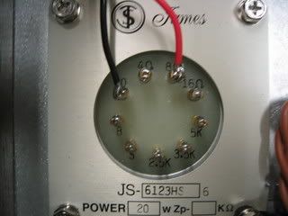
Couple of noob questions coming up. For the OT I am thinking the B goes to the B+ and the 2.5K goes to the output tube. Is this correct?
![]() by ecir38 » Tue Jun 24, 2008 4:49 pm
by ecir38 » Tue Jun 24, 2008 4:49 pm
![]() by Blackburn Audio » Tue Jun 24, 2008 6:16 pm
by Blackburn Audio » Tue Jun 24, 2008 6:16 pm

![]() by ecir38 » Sat Jul 12, 2008 10:40 pm
by ecir38 » Sat Jul 12, 2008 10:40 pm
Users browsing this forum: No registered users and 15 guests