Shannon's board availability for st-70
14 posts
• Page 1 of 1
Shannon's board availability for st-70
![]() by tomsamps » Mon Sep 05, 2016 7:49 am
by tomsamps » Mon Sep 05, 2016 7:49 am
It appears that consensus is that the diytube driver board and the triode cap board are the favorites. Since I am looking to upgrade my st-70 I am looking for the boards. Is the diytube board available somewhere or will it be again soon? Thanks
- tomsamps
- Posts: 4
- Joined: Sat Jul 09, 2011 2:07 pm
- Location: Los Angeles
Re: Shannon's board availability for st-70
![]() by tomsamps » Tue Sep 06, 2016 2:26 pm
by tomsamps » Tue Sep 06, 2016 2:26 pm
OK - I guess I was a bit late and there will not be more of these made. So short of someone with a bit of a stash that would part with one (never hurts to ask) I will be in the market for another driver board. The DynaMull board looks new and interesting. Any feedback on that? Thanks
- tomsamps
- Posts: 4
- Joined: Sat Jul 09, 2011 2:07 pm
- Location: Los Angeles
Re: Shannon's board availability for st-70
![]() by WA4SWJ » Wed Sep 07, 2016 6:07 am
by WA4SWJ » Wed Sep 07, 2016 6:07 am
I have an octal Dynamutt board that I have not had time to build yet. I am going to use it in an 807 P-P amp. I have all the parts, I'm just lazy lately! One of these days when I get to it I'll post some info. I know this isn't much help.
A comment though - the board looks great and the circuit does also. The board is nicely made.
Good luck!
A comment though - the board looks great and the circuit does also. The board is nicely made.
Good luck!
Ed Long
-

WA4SWJ - KT88
- Posts: 650
- Joined: Mon Dec 27, 2004 8:39 pm
- Location: Belleview, FL
Re: Shannon's board availability for st-70
![]() by dspth » Sat Sep 10, 2016 2:18 am
by dspth » Sat Sep 10, 2016 2:18 am
There are lots of positive reviews for both Dynamutt and Dynamull here on diytube and
on Audiokarma.
http://audiokarma.org/forums/index.php? ... ull&o=date
on Audiokarma.
http://audiokarma.org/forums/index.php? ... ull&o=date
- dspth
- Posts: 18
- Joined: Fri Dec 18, 2009 11:51 pm
- Location: India
Re: Shannon's board availability for st-70
![]() by EWBrown » Sat Sep 10, 2016 8:07 pm
by EWBrown » Sat Sep 10, 2016 8:07 pm
I have three of the old Rev A Brown board driver boards, all components installed and soldered.
There are a few different cap and resistor values in the rev B (red board), for fine tuning the circuit.
I originally built these boards about ten years ago, for a project, which later fell through, as the customer who originally
wanted me to build three ST-70s for him, bailed out on me. Fortunately before I bought the chassis and transformers...
viewtopic.php?f=6&t=597
I have copies of the rev A and rev B manuals, including one from "The Tube Zone"
/ed B in NC
Last edited by EWBrown on Sat Oct 01, 2016 6:00 pm, edited 2 times in total.
Real Radios Glow in the Dark
-

EWBrown - Insulator & Iron Magnate
- Posts: 6389
- Joined: Wed Mar 19, 2003 6:03 am
- Location: Now located in Clay County, NC !
Re: Shannon's board availability for st-70
![]() by dannyr » Mon Sep 12, 2016 12:19 am
by dannyr » Mon Sep 12, 2016 12:19 am
Hi, with a few traces cut etc you can pretty easily turn a KTA 70 board sold at http://www.classicvalve.ca into Shannon's design. I can post pictures and maybe instructions if anyone is really interested in doing such. I actually did it years ago to one.
Ed, what are you looking to get for a REV A stuffed board?
Ed, what are you looking to get for a REV A stuffed board?
- dannyr
- Posts: 68
- Joined: Mon Mar 30, 2009 9:09 pm
Re: Shannon's board availability for st-70
![]() by tomsamps » Mon Sep 12, 2016 8:05 am
by tomsamps » Mon Sep 12, 2016 8:05 am
Ed I am interested also!
- tomsamps
- Posts: 4
- Joined: Sat Jul 09, 2011 2:07 pm
- Location: Los Angeles
Re: Shannon's board availability for st-70
![]() by Quad » Mon Sep 12, 2016 11:08 am
by Quad » Mon Sep 12, 2016 11:08 am
dannyr wrote:Hi, with a few traces cut etc you can pretty easily turn a KTA 70 board sold at http://www.classicvalve.ca into Shannon's design. I can post pictures and maybe instructions if anyone is really interested in doing such. I actually did it years ago to one.
Danny, do post the details. I am sure it will help someone in future.
It was news to me that Shannon's board is no longer available.
- Quad
- KT88
- Posts: 254
- Joined: Mon Jan 14, 2008 6:54 am
- Location: India
Re: Shannon's board availability for st-70
![]() by dannyr » Mon Sep 12, 2016 1:52 pm
by dannyr » Mon Sep 12, 2016 1:52 pm
Okay. I'll take some pictures soon. I believe only two traces have to be cut.
- dannyr
- Posts: 68
- Joined: Mon Mar 30, 2009 9:09 pm
Re: Shannon's board availability for st-70
![]() by dannyr » Mon Sep 12, 2016 10:15 pm
by dannyr » Mon Sep 12, 2016 10:15 pm
Kta70 = DIYTube part
R1 = R1, R2 1k
R2 = R3, R4 475k
R21 = R11, R12 100k
R3 = R7, R8 1k
R4 = R5, R6 100
R5 = R9 with C3 across it, R10 with C4 across 2.7k, 220pf
R9, R10 = Jumpers
R6 = R13, R14 5.6k
R8 = R15, R16 1m
R11, R12 = R19, R20, R21, R22 43K 2w
R13, R14 = R23, R24, R25, R26 150k
R12, R15 = 1k 1/2w (need 4)
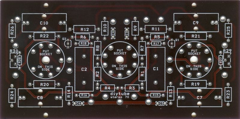
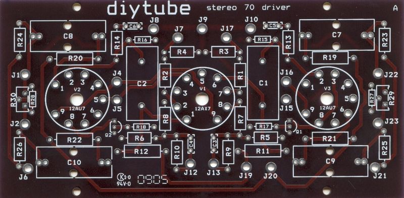
R7 = R18, R19, Q1, Q2 (resistor and leg LM334 soldered together and inserted to R7’s pad closest to the boards 12ax7, the other end of resistor soldered to the middle leg of LM334 and remaining outter leg of the LM334 to the other R7 pad) (see top picture for orientation)
C1 = C5, C6 330pf
C2 = Jumper
C4, C5 = C8, C9, C10, C11 .047uf
Both kta middle B+ points = 300v
Both Outter B+ points = 350v
One .1uf (DIYtube C1) capacitor soldered from pin 1 of the 12ax7 to any pad that connects to pin 2 of the 12au7 on the side closest to it under the board (See jpg) insulate the capacitor’s leads
One .1uf (DIYtube C2) capacitor soldered from pin 6 of the 12ax7 to any pad that connects to pin 2 of the other 12au7 on the side closest to it under the board (see jpg) insulate the capacitor’s leads.
Left bias pot going to one of the KTA70’s boards bias spots on the left and then a wire going from it to the other bias pad on the same side.
Right bias pot going to one of the KTA70’s board’s bias spots on the right side of the board then a wire going from it to the second bias pad on the same side.
For the trim pot I drilled a small hole on top of the board, please look at the pics, and then under the board ran one outter leg to the KTA C4 and R15 meet and the other side of the trim to where C5 and R12 meet. The middle to DIY R27 or R28 and the other end of the resistor to a ground point with a small wire run. I glued the trim pot on with the top with some gorilla glue.
Cut the two traces that are black in the below picture


R1 = R1, R2 1k
R2 = R3, R4 475k
R21 = R11, R12 100k
R3 = R7, R8 1k
R4 = R5, R6 100
R5 = R9 with C3 across it, R10 with C4 across 2.7k, 220pf
R9, R10 = Jumpers
R6 = R13, R14 5.6k
R8 = R15, R16 1m
R11, R12 = R19, R20, R21, R22 43K 2w
R13, R14 = R23, R24, R25, R26 150k
R12, R15 = 1k 1/2w (need 4)
R7 = R18, R19, Q1, Q2 (resistor and leg LM334 soldered together and inserted to R7’s pad closest to the boards 12ax7, the other end of resistor soldered to the middle leg of LM334 and remaining outter leg of the LM334 to the other R7 pad) (see top picture for orientation)
C1 = C5, C6 330pf
C2 = Jumper
C4, C5 = C8, C9, C10, C11 .047uf
Both kta middle B+ points = 300v
Both Outter B+ points = 350v
One .1uf (DIYtube C1) capacitor soldered from pin 1 of the 12ax7 to any pad that connects to pin 2 of the 12au7 on the side closest to it under the board (See jpg) insulate the capacitor’s leads
One .1uf (DIYtube C2) capacitor soldered from pin 6 of the 12ax7 to any pad that connects to pin 2 of the other 12au7 on the side closest to it under the board (see jpg) insulate the capacitor’s leads.
Left bias pot going to one of the KTA70’s boards bias spots on the left and then a wire going from it to the other bias pad on the same side.
Right bias pot going to one of the KTA70’s board’s bias spots on the right side of the board then a wire going from it to the second bias pad on the same side.
For the trim pot I drilled a small hole on top of the board, please look at the pics, and then under the board ran one outter leg to the KTA C4 and R15 meet and the other side of the trim to where C5 and R12 meet. The middle to DIY R27 or R28 and the other end of the resistor to a ground point with a small wire run. I glued the trim pot on with the top with some gorilla glue.
Cut the two traces that are black in the below picture
- dannyr
- Posts: 68
- Joined: Mon Mar 30, 2009 9:09 pm
Re: Shannon's board availability for st-70
![]() by dannyr » Mon Sep 12, 2016 10:20 pm
by dannyr » Mon Sep 12, 2016 10:20 pm
If anyone needs and help please let me know.
- dannyr
- Posts: 68
- Joined: Mon Mar 30, 2009 9:09 pm
Re: Shannon's board availability for st-70
![]() by EWBrown » Wed Sep 14, 2016 7:41 am
by EWBrown » Wed Sep 14, 2016 7:41 am
Two of the boards are assembled "Dynaco Style" with all components on the top, and one has the components on the bottom - to accommodate one of the
aftermarket metal screen board covers. They are assembled correctly (Rev A) , but have not been tested in-circuit.


I'm looking for $70 each, which includes the USPS priority mail shipping ($6.95) within CONUS.
Update 10/01/16: All boards are sold, no more available..
/ed B in NC
aftermarket metal screen board covers. They are assembled correctly (Rev A) , but have not been tested in-circuit.
I'm looking for $70 each, which includes the USPS priority mail shipping ($6.95) within CONUS.
Update 10/01/16: All boards are sold, no more available..
/ed B in NC
Last edited by EWBrown on Sun Oct 02, 2016 6:45 pm, edited 1 time in total.
Real Radios Glow in the Dark
-
EWBrown - Insulator & Iron Magnate
- Posts: 6389
- Joined: Wed Mar 19, 2003 6:03 am
- Location: Now located in Clay County, NC !
Re: Shannon's board availability for st-70
![]() by VuTran2003 » Sat Oct 01, 2016 7:20 pm
by VuTran2003 » Sat Oct 01, 2016 7:20 pm
I need buy 1pcs pcb board for st-70
- VuTran2003
- Posts: 2
- Joined: Sat May 21, 2016 9:54 pm
Re: Shannon's board availability for st-70
![]() by EWBrown » Sun Oct 02, 2016 6:44 pm
by EWBrown » Sun Oct 02, 2016 6:44 pm
Last one is already sold!
/ed B
/ed B
Real Radios Glow in the Dark
-
EWBrown - Insulator & Iron Magnate
- Posts: 6389
- Joined: Wed Mar 19, 2003 6:03 am
- Location: Now located in Clay County, NC !
14 posts
• Page 1 of 1
Who is online
Users browsing this forum: No registered users and 4 guests