This is where I'm at now... I'll probably clean things up at some point.
![]() by JimDaBomb » Sat Jun 21, 2014 10:55 am
by JimDaBomb » Sat Jun 21, 2014 10:55 am
![]() by Shannon Parks » Sat Jun 21, 2014 1:36 pm
by Shannon Parks » Sat Jun 21, 2014 1:36 pm
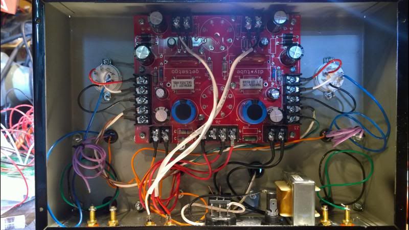
JimDaBomb wrote:I see where the yellow marked one goes but are the other two red wires different? Does it matter which sides they go to?
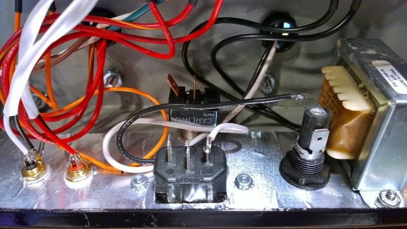
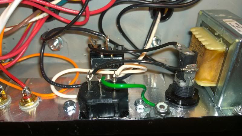
JimDaBomb wrote:I'm also a little confused about how to wire in the on/off switch and IEC, and do I have to ground to the chassis somewhere?

![]() by TomMcNally » Sat Jun 21, 2014 2:00 pm
by TomMcNally » Sat Jun 21, 2014 2:00 pm

![]() by JimDaBomb » Sat Jun 21, 2014 2:30 pm
by JimDaBomb » Sat Jun 21, 2014 2:30 pm
![]() by JimDaBomb » Sat Jun 21, 2014 3:05 pm
by JimDaBomb » Sat Jun 21, 2014 3:05 pm
![]() by TomMcNally » Sat Jun 21, 2014 3:18 pm
by TomMcNally » Sat Jun 21, 2014 3:18 pm

![]() by JimDaBomb » Sat Jun 21, 2014 3:27 pm
by JimDaBomb » Sat Jun 21, 2014 3:27 pm
![]() by Shannon Parks » Sat Jun 21, 2014 4:52 pm
by Shannon Parks » Sat Jun 21, 2014 4:52 pm
TomMcNally wrote:The schematic has two right inputs, just noticed that.
 Better than two wrong inputs.
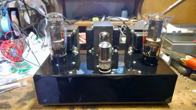
JimDaBomb wrote:Okay, I fixed it.. I had one of the inputs wired wrong. It's making some beautiful music right now warming up with Pandora. Unfortunately I sold my Klipsch La Scala's yesterday so I never got to hear them with the amp and I'm running some inefficient Pioneers right now, the Andrew Jones ones but I ordered some Tekton Lores so hopefully those will be here in a few days. I can tell this is a great amp and it was really pretty simple to build. Thank you so much for this design and the help and allowing me to finally hear and have an SET amp, otherwise I could never afford an amp of this quality.
![]() by JimDaBomb » Sun Jun 22, 2014 6:58 am
by JimDaBomb » Sun Jun 22, 2014 6:58 am
![]() by Shannon Parks » Mon Jun 23, 2014 9:49 am
by Shannon Parks » Mon Jun 23, 2014 9:49 am
![]() by JimDaBomb » Mon Jun 23, 2014 12:26 pm
by JimDaBomb » Mon Jun 23, 2014 12:26 pm
Users browsing this forum: No registered users and 1 guest