What is the overall gain of this?
What is the gain of the bass-boost and at what frequency?
Looks awesome!
First Budgie Preamplifier Post
52 posts
• Page 2 of 4 • 1, 2, 3, 4
Re: First Budgie Preamplifier Post
![]() by tomlang » Sat Jan 04, 2014 7:43 pm
by tomlang » Sat Jan 04, 2014 7:43 pm
-

tomlang - Posts: 192
- Joined: Sat Sep 26, 2009 8:14 pm
- Location: Augusta, GA
Re: First Budgie Preamplifier Post
![]() by Shannon Parks » Sun Jan 05, 2014 9:40 am
by Shannon Parks » Sun Jan 05, 2014 9:40 am
IceFyre13th wrote:Shannon,
What are the dimensions of the PCB? I am going to build in a larger sized chassis so I can add a Phono stage in it later on........that leads to another idea, 24 volt phono preamp to match the power supply requirements of this build.
Dims are 8" by 4.25". I've upped a FPE file of just the PCB so all the relevant dims are therein for making any custom chassis (and it can be exported to DXF need be).
http://www.diytube.com/arduino/pcbdims.fpd
Unfortunately, I've determined to bum you out with the 24V supply with the DIY Budgie phono.
 I just can't see a good "same chassis" cooperation, as 24V doesn't work for the filaments and is far too low for the 6922 plates, where 48V is really a minimum. Transconductance really starts dropping at lower currents even *if* the small signals were linear enough. And the Gm is the magic of it all. I think a little DIY JFET phono module would be the ticket here, if not a separate Budgie phono.
Meanwhile, the 12B4s are freaky in that they can work at these low voltages (typically 17V drop across the tube). Perveance is a beautiful thing!
Shannon
- designer of fine tube audio gear at (((parks audio)))
- founder and admin of the diytube forums
-

Shannon Parks - Site Admin
- Posts: 3764
- Joined: Tue Mar 18, 2003 5:40 pm
- Location: Poulsbo, Washington
Re: First Budgie Preamplifier Post
![]() by Shannon Parks » Sun Jan 05, 2014 10:05 am
by Shannon Parks » Sun Jan 05, 2014 10:05 am
tomlang wrote:What is the overall gain of this?
What is the gain of the bass-boost and at what frequency?
Looks awesome!
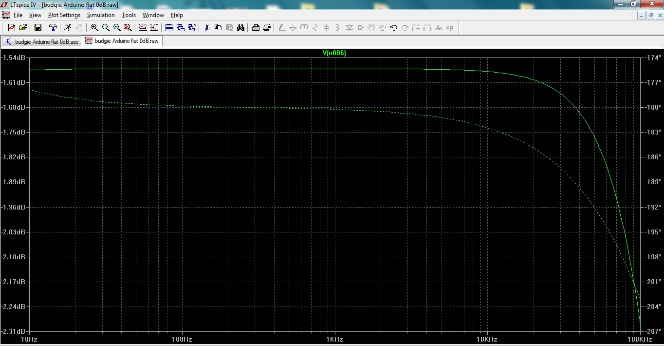
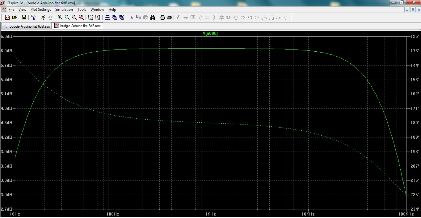
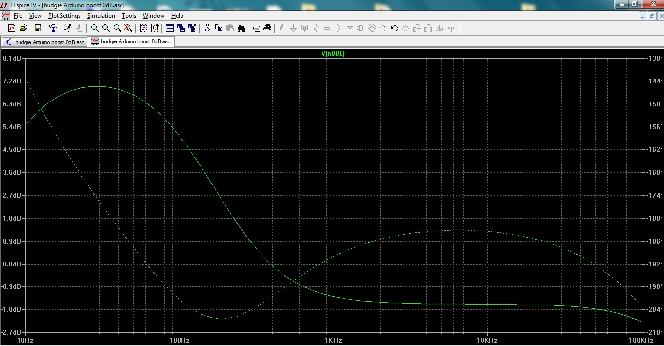
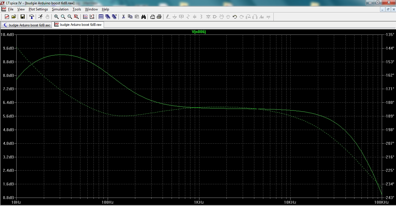
The current design is for +0dB and +6dB gain. I've attached shots to show the boost sims (which swept exactly the same on the audio analyzer). Note that the feedback capacitor doesn't change, while the resistor does, so our RC time constant changes affecting bass boost. So we have four settings: Flat 0dB, Flat 6dB, Boost 0dB and Boost 6dB. I normally use Boost 6dB for everything. The little boost helps my smaller bass reflex speakers even with CD source. I think in the future I just might have the gain determined by a resistive divider on the input (i.e. CDs). The Boost 0dB is mega boost - useful for the most rolled off records I own, like early 60's Vanguard.
I needed the gain to stay within 6dB as the boost would be useless on both settings otherwise (either way too little on one setting or waaay too much on the other). 12B4s can do 15dB gain with no feedback, for what is it worth. I'll upload a LTSpice file soon that will let folks tweak to their hearts content (adjusting the feedback resistors and cap).
Shannon
Flat 0dB
Flat 6dB
Boost 0dB
Boost 6dB
- designer of fine tube audio gear at (((parks audio)))
- founder and admin of the diytube forums
-
Shannon Parks - Site Admin
- Posts: 3764
- Joined: Tue Mar 18, 2003 5:40 pm
- Location: Poulsbo, Washington
Re: First Budgie Preamplifier Post
![]() by EWBrown » Sun Jan 05, 2014 7:15 pm
by EWBrown » Sun Jan 05, 2014 7:15 pm
What is the optimum 12B4A plate current for 24VDC operation, and what would be the SWAG setting for the cathode trimpots? 
I'm thinking of trying a bare-bones basic version, without the micro-controller, with just the active tube section.
24V power supply would consist of eight series-connected 5000 mA/H Li-Ion 18650 size rechargeables.
I've found some of the rather "elusive" battery holders, and I have a couple of small "smart" chargers which can charge four cells at a time.
All found on e-bay, US sellers, quick & "free" shipping
No AC, no SMPS, No hum, no PSU noise of any kind. Just black background bliss

e-place for the Li-Ion cells: http://www.ebay.com/itm/8pcs-Ultra-Fire ... 2c757c8a59
e-place for the charger: http://www.ebay.com/itm/NEW-NITECORE-i4 ... 5afa1aa615
or: http://www.ebay.com/itm/NEW-NITECORE-i4 ... 1e82d30685
/ed B
I'm thinking of trying a bare-bones basic version, without the micro-controller, with just the active tube section.
24V power supply would consist of eight series-connected 5000 mA/H Li-Ion 18650 size rechargeables.
I've found some of the rather "elusive" battery holders, and I have a couple of small "smart" chargers which can charge four cells at a time.
All found on e-bay, US sellers, quick & "free" shipping
No AC, no SMPS, No hum, no PSU noise of any kind. Just black background bliss
e-place for the Li-Ion cells: http://www.ebay.com/itm/8pcs-Ultra-Fire ... 2c757c8a59
e-place for the charger: http://www.ebay.com/itm/NEW-NITECORE-i4 ... 5afa1aa615
or: http://www.ebay.com/itm/NEW-NITECORE-i4 ... 1e82d30685
/ed B
Last edited by EWBrown on Thu Jan 09, 2014 6:11 pm, edited 3 times in total.
Real Radios Glow in the Dark
-

EWBrown - Insulator & Iron Magnate
- Posts: 6389
- Joined: Wed Mar 19, 2003 6:03 am
- Location: Now located in Clay County, NC !
Re: First Budgie Preamplifier Post
![]() by Shannon Parks » Mon Jan 06, 2014 5:49 am
by Shannon Parks » Mon Jan 06, 2014 5:49 am
EWBrown wrote:What is the optimum 12B4A plate current for 24VDC operation, and what would be the SWAG setting for the cathode trimpots?
The 12B4s are biased around 5mA, determined by the active load current source ((red LED - Vbe of transistor) / 210 ohm resistor). The cathode trimpot then adjusts for lowest distortion. It can initially be adjusted to 350 ohms. Using a input sine wave (from a cell phone function generator app) adjust for maximum output measured with any DMM. This will be the lowest distortion. But I plan to go through my stash of RCA, Sylvania and GE 12B4 tubes. I think the tubes bias similarly from the same manufacturer. So RCAs might 350 ohms and GEs 275 ohms, etc. I'll do this soon. The plate voltage will be in the 15V to 19V range. Any higher will risk early clipping at the CCS.
EWBrown wrote:I'm thinking of trying a bare-bones basic version, without the micro-controller, with just the active tube section. 24V power supply would consist of eight series-connected 5000 mA/H Li-Ion 18650 size rechargeables. I've found some of the rather "elusive" battery holders, and I have a couple of small "smart" chargers which can charge four cells at a time. All found on e-bay, US sellers, quick & "free" shipping.
I researched those recently when my good LED flashlight died - very nifty batteries.
Shannon
- designer of fine tube audio gear at (((parks audio)))
- founder and admin of the diytube forums
-
Shannon Parks - Site Admin
- Posts: 3764
- Joined: Tue Mar 18, 2003 5:40 pm
- Location: Poulsbo, Washington
Re: First Budgie Preamplifier Post
![]() by IceFyre13th » Thu Jan 09, 2014 12:22 pm
by IceFyre13th » Thu Jan 09, 2014 12:22 pm
Well I will say, you ship fast..............PCB's made it to me Monday, still waiting for the other parts.
I did take your advice on the phono stage, I found a kit that runs on the same 24 volts DC and has been highly recommend by other DIYer's. Not JFET, but the "circuit topology that uses low noise audio
opamps implementing passive split equalization filters and to provide a low output impedance". In quotes cut and past from the manual of the kit, not sure if I should post the brand or link here as this is your site.
Everything will be mounted in a Hammond Walnut Chassis ( http://www.hammondmfg.com/HWCHAS.htm ), Mouser had a few in stock, so it was easy to add to the rest of the order.
Need your opinion on a power supply, I have a few Astrodyne OFM60-240 ( http://ecatalog.astrodyne.com/usa/open- ... /OFM60-240 ) I could use. Do you think this will be ok? Yes I would shield it inside the chassis to help prevent noise, in its own Faraday shield so to speak.
I will post pictures of the build, just cant wait for the final result......
- IceFyre13th
- Posts: 48
- Joined: Tue Sep 03, 2013 11:05 am
Re: First Budgie Preamplifier Post
![]() by Shannon Parks » Fri Jan 10, 2014 1:27 pm
by Shannon Parks » Fri Jan 10, 2014 1:27 pm
IceFyre13th wrote:I did take your advice on the phono stage, I found a kit that runs on the same 24 volts DC and has been highly recommend by other DIYer's. Not JFET, but the "circuit topology that uses low noise audio opamps implementing passive split equalization filters and to provide a low output impedance". In quotes cut and past from the manual of the kit, not sure if I should post the brand or link here as this is your site.
No problem at all - please post the link for the phono stage. Sounds perfect.
IceFyre13th wrote:Need your opinion on a power supply, I have a few Astrodyne OFM60-240 ( http://ecatalog.astrodyne.com/usa/open- ... /OFM60-240 ) I could use. Do you think this will be ok? Yes I would shield it inside the chassis to help prevent noise, in its own Faraday shield so to speak.
What size Hammond chassis will you be using? I just did a SWAG type test, and laid the desktop supply on the top and sides of the Budgie preamp, and as long as I didn't get near the tubes it didn't pick up (much) noise. Since you have them already, why not give them a try?
Shannon
- designer of fine tube audio gear at (((parks audio)))
- founder and admin of the diytube forums
-
Shannon Parks - Site Admin
- Posts: 3764
- Joined: Tue Mar 18, 2003 5:40 pm
- Location: Poulsbo, Washington
Re: First Budgie Preamplifier Post
![]() by IceFyre13th » Fri Jan 10, 2014 2:45 pm
by IceFyre13th » Fri Jan 10, 2014 2:45 pm
The Phono amp I will be using is the Bugle 2 ( http://www.hagtech.com/bugle2.html )
Hammond Chassis is 17" X 10 "
Hammond Chassis is 17" X 10 "
- IceFyre13th
- Posts: 48
- Joined: Tue Sep 03, 2013 11:05 am
Re: First Budgie Preamplifier Post
![]() by Shannon Parks » Fri Jan 10, 2014 4:12 pm
by Shannon Parks » Fri Jan 10, 2014 4:12 pm
IceFyre13th wrote:The Phono amp I will be using is the Bugle 2 ( http://www.hagtech.com/bugle2.html )
Hammond Chassis is 17" X 10 "
Very cool! I'm a big fan of Jim Hagerman's work and was familiar with it but I didn't realize it was a 24V single supply board. That'll be perfect. And you'll have plenty of room with that chassis.
Shannon
- designer of fine tube audio gear at (((parks audio)))
- founder and admin of the diytube forums
-
Shannon Parks - Site Admin
- Posts: 3764
- Joined: Tue Mar 18, 2003 5:40 pm
- Location: Poulsbo, Washington
Re: First Budgie Preamplifier Post
![]() by IceFyre13th » Wed Jan 22, 2014 12:32 pm
by IceFyre13th » Wed Jan 22, 2014 12:32 pm
Just about have everything I need to start my build, still have to order my front and back panel from FPE. Still designing these.
But, before I do there is something I would like to add to the design. I would like to add a relay that control's a 120 VAC socket on the back of the unit to turn on and off my tube amplifier.
I see there are unused digital pins on the Nano (D0, D1, D2), my thought would be to use one pin to drive a transistor (2n2222 NPN) that would drive the relay coil with a delay. This would allow the preamp to be fully on before turning on the amp (eliminate thumps).
Say pin D2 to a 1K ohm resistor to the base of the 2N2222. Emitter of transistor to ground. Collector to one side of the relays coil. Other side of relay coil to DC volt (5 or 24 volts?). And of course a 1N4003 diode across the coil. The Relay would be a 5 or 24 volt coil relay with 120 VAC 10 amp contacts DPST (I like switching both leads on / off on AC lines, seems safer to me).
Problem is, I am new to Arduino....I know the basics, but your sketch is way more complicated than anything I have done so I am afraid to edit it to do this......more like I have no idea how to do it or even where I should add this to the sketch. If I had to write a sketch just for a relay.....OK, adding delay, sure.....incorporating this to your sketch, where / how
Sample Sketch I know how to do:
int transistorBasePin = 2;
void setup()
{
pinMode(transistorBasePin, OUTPUT);
}
void loop()
{
digitalWrite(transistorBasePin, LOW);
delay(5000);
digitalWrite(transistorBasePin, HIGH);
}
All I have here is wait 5 seconds then turn on relay.
What I envision it being:
1. Turn on preamp from standby.
2. This would then wait a few seconds (10 to 30 ) to allow the preamp to "warm up" and be ready to go before turning on the AC sockets relay to allow the amplifier to turn on. Any one of the unused pins and a 5 volt coil relay with 120 VAC 10 amp contacts DPST (I like switching both leads on / off on AC lines, seems safer to me).
3. When the preamp is turned off it will also turn off the AC relay.
Any help you can give me.............please.
- IceFyre13th
- Posts: 48
- Joined: Tue Sep 03, 2013 11:05 am
Re: First Budgie Preamplifier Post
![]() by Shannon Parks » Thu Jan 23, 2014 11:59 am
by Shannon Parks » Thu Jan 23, 2014 11:59 am
IceFyre13th wrote:I see there are unused digital pins on the Nano (D0, D1, D2), my thought would be to use one pin to drive a transistor (2n2222 NPN) that would drive the relay coil with a delay. This would allow the preamp to be fully on before turning on the amp (eliminate thumps).
D0 and D1 are part of the serial communications via USB, so leave those alone. The two available pins are D2 (which can be interrupt driven) and A7 (which can be used as an analog or digital pin).
The whole void setup has been offloaded to "setup.h". In setup.h, you'll see:
- Code: Select all
//set up the LCD, splash screens and tube delay
  Setup_LCD();
This is the LCD already doing a 15 second countdown to warm up the 12B4s. They'd screech something awful otherwise. You could just put your code there:
- Code: Select all
//set up the LCD, splash screens and tube delay
  Setup_LCD();

//Energize 120VAC Relay added by IceFyre13th 1-23-2014
pinMode(transistorBasePin, OUTPUT);
digitalWrite(transistorBasePin, HIGH);
You'd declare at the top of mem.h:
- Code: Select all
// Digital pin assignment notes
// Analog pins used as digital are considered D14 thru D18 (e.g. A0 is D14)
//
// D0 and D1 are reserved for serial bus (TX & RX)
// D13 can only used as an output as there's a status LED is on that port
// SPI bus is not used other than for digital pins (no MOSI, MISO or SCK)
// D2 is the only spare pin, but it supports hardware interrupts and PWM
const byte transistorBasePin = 2;  //added by IceFyre13th 1-23-2014
const byte CLK_595 = 3;
const byte LATCH_595 = 4;
const byte ENABLE_595 = 5;
const byte POWER_LED = 6;
So pretty easy stuff. The tricky part is sourcing an adequate relay as power amps can be current hogs. And the power down scheme might need to be more elegant.
Shannon
- designer of fine tube audio gear at (((parks audio)))
- founder and admin of the diytube forums
-
Shannon Parks - Site Admin
- Posts: 3764
- Joined: Tue Mar 18, 2003 5:40 pm
- Location: Poulsbo, Washington
Re: First Budgie Preamplifier Post
![]() by IceFyre13th » Thu Jan 23, 2014 3:49 pm
by IceFyre13th » Thu Jan 23, 2014 3:49 pm
Thank you, once I read what you said to do I thought to myself......DUH.....LOL.
Being new to code writing though I just could "not see the forest for the trees"
I will let you know how it works out.
BTW, Relays in consideration are these http://www.mouser.com/ProductDetail/Omr ... 2qZA3ZjMH6
With this socket http://www.mouser.com/ProductDetail/Omr ... pAXg%3d%3d
or http://www.mouser.com/ProductDetail/Omr ... 52baYPM%3d
10 amp contact rating for 380 VAC or 125 VDC, Coil is 24 V @ 21.6 mA......should be enough for my SET Amp
- IceFyre13th
- Posts: 48
- Joined: Tue Sep 03, 2013 11:05 am
Re: First Budgie Preamplifier Post
![]() by IceFyre13th » Fri Feb 14, 2014 11:49 am
by IceFyre13th » Fri Feb 14, 2014 11:49 am
Front panel express parts are ordered, so I figured why not show the concept of my preamplifier build.
The attached JPEG's were made in SolidWorks, I am a mechanical engineer by trade.
Everything should be in my hands by the middle of next week so I can start building......prefect timing too as my other project is going to the paint shop so I will have something to do!!!
The attached JPEG's were made in SolidWorks, I am a mechanical engineer by trade.
Everything should be in my hands by the middle of next week so I can start building......prefect timing too as my other project is going to the paint shop so I will have something to do!!!
- Attachments
-
- Bottom View showing Budgie Pre-Amp PCB, Bugle II PCB, and Power supply
- 4X Dragon Pre-Amplifier Assembly 3.JPG (280.81 KiB) Viewed 18636 times
-
- Rear Connections
- 4X Dragon Pre-Amplifier Assembly 2.JPG (248.26 KiB) Viewed 18636 times
-
- 4X Dragon Pre-Amplifier Assembly 1.JPG (202.22 KiB) Viewed 18636 times
- IceFyre13th
- Posts: 48
- Joined: Tue Sep 03, 2013 11:05 am


52 posts
• Page 2 of 4 • 1, 2, 3, 4
Who is online
Users browsing this forum: No registered users and 0 guests