 [/url]
Milliamp guitar amp question
8 posts
• Page 1 of 1
Milliamp guitar amp question
![]() by Austin Translation » Thu Aug 11, 2011 12:00 pm
by Austin Translation » Thu Aug 11, 2011 12:00 pm
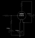
In this schematic I am having trouble understanding why the 12au7 section of the tube does not connect like a normal se power tube section with the B+ passing though the output transformer primary. Since it uses a resistor like a voltage amp would, does this not needlessly sacrifice power and volume to heat dissipation? [/url]
[/url]-
Austin Translation - Posts: 32
- Joined: Wed Jun 29, 2011 9:57 pm
![]() by mashaffer » Thu Aug 11, 2011 3:52 pm
by mashaffer » Thu Aug 11, 2011 3:52 pm
Looks like a variation on the old parafeed circuit. usually you will see it with the blocking cap in the positive side of the OPT primary which would make its purpose more clear. The cap keeps DC out of the OPTs. This is usually done so that an OPT without a gapped core can be used.
The other difference is that the plate load in a parafeed is usually a choke to conserve B+ and to limit wasted power dissipation but the concept is the same. Since the idle current is so low in this design the difference isn't nearly as critical.
mike
The other difference is that the plate load in a parafeed is usually a choke to conserve B+ and to limit wasted power dissipation but the concept is the same. Since the idle current is so low in this design the difference isn't nearly as critical.
mike
- mashaffer
- Posts: 34
- Joined: Wed May 28, 2008 5:02 pm
![]() by EWBrown » Thu Aug 11, 2011 4:21 pm
by EWBrown » Thu Aug 11, 2011 4:21 pm
A simple improvement would be to connect the coupling cap from the plate to the "top" of OPT primary , and the "cold end" of the OPT to the cathode, rather than to signal ground. That eliminates the cathode resistor and cap from the ausio signal path.
Also the 15K plate resistor could be replaced with one of the small 150H, 8 mA Hammond chokes, these have a DC resistance around 4K ohms. The cathode resistance would have to be adjusted slightly, but then that is already an adjustable resistor.
Another alternate approach would be to use one of the 10M45S CCS dwevices, set for approximatly 10 mA in place of the 15K resistor.
12DW7 is essentially half a 12AX7 and half a 12AU7 sharing the same bottle. Equivalents are the 7247 and the J/J ECC832.
With any of these tubes, the power output will be miniscule, but it should be very good for a headphone practice amp.
/ed B
Real Radios Glow in the Dark
-

EWBrown - Insulator & Iron Magnate
- Posts: 6389
- Joined: Wed Mar 19, 2003 6:03 am
- Location: Now located in Clay County, NC !
![]() by Austin Translation » Thu Aug 11, 2011 6:34 pm
by Austin Translation » Thu Aug 11, 2011 6:34 pm
Thanks for the replies. Is there any reason not to connect the 12au7 side like this: What am I missing? That pic is from http://www.tubecad.com/september99/page11.html
I would just adjust the value of the resistors and ignore the missing screen grid thats strapped to the plate anyway right? Whats the point of doing it the other way?
I have a tiny little output tranny I have from an old sears intercom, it was driven by a single 50B5, (that I broke when i attempted to straighten the pins) so might the impedance be close enough to work on the 12au7?
What am I missing? That pic is from http://www.tubecad.com/september99/page11.html
I would just adjust the value of the resistors and ignore the missing screen grid thats strapped to the plate anyway right? Whats the point of doing it the other way?
I have a tiny little output tranny I have from an old sears intercom, it was driven by a single 50B5, (that I broke when i attempted to straighten the pins) so might the impedance be close enough to work on the 12au7?
-
Austin Translation - Posts: 32
- Joined: Wed Jun 29, 2011 9:57 pm
![]() by EWBrown » Fri Aug 12, 2011 7:21 am
by EWBrown » Fri Aug 12, 2011 7:21 am
The 50B5 (and 50C5) is specifieded for a 2.5K primary OPT, and the most common small speaker impedance was typically 3.2 or 4 ohms back then. So, if this is the situation, then the OPT, feeding an 8 ohm speaker, would "reflect" between 5K and 6.25K back to the primary . THis is simply a matter of ratios, which in turn is a square of the ratio of the numbers of turns on each winding.
A quick and simple way to approximate the transformer's turns ratio is to feed the primary with a known, low (12-24 VAC) AC voltage, and then measure the secondary's AC voltage, and then divide the primary voltage reading by the secondary's voltage. This will give the primary: secondary turns ratio. Square that number, then multiply by the speaker's nominal impedance, that will give you the effective primary impedance.
For example, and I'm using "round" numbers here to keep the math simple, there is 12.5VAC across the primary, and the secondary measures at 0.50 VAC. That would be a voltage (and turns) ratio of 12.5: 0.5, or 25:1.
25 squared is 625, which multiplied by 8 (ohms) would be 5.0K ohms.
The main reason not to connect the output (12AU7) section as in your example, would be that the DC resistance of the OPT would be far too low (typically 100 to 300 ohms) and the triode section would be over-stressed from excessive plate current , and would be damaged in short order. The 15K plate resistor limits the plate current to 10 mA, and with about 150VDC between the plate and the cathode, that would be 1.5 watts plate dissipation.
The small plate choke I mentioned earlier has about 4 K ohms DC resistance, and the cathode resistor could be changed in order to keep the plate dissipation within safe limits, but it sould be best to start out with the 15K resistor, get it working, then try the modifications, one at a time, later on.
/ed B
Real Radios Glow in the Dark
-
EWBrown - Insulator & Iron Magnate
- Posts: 6389
- Joined: Wed Mar 19, 2003 6:03 am
- Location: Now located in Clay County, NC !
![]() by Austin Translation » Sun Aug 14, 2011 10:43 am
by Austin Translation » Sun Aug 14, 2011 10:43 am
Should I build a this using the 6fd7 tube? I just discovered it. A guitar would need more gain than the 1st section could provide so another tube would be needed correct? Any thoughts on this tube for audio? It says vertical deflection tube. Thank you
-
Austin Translation - Posts: 32
- Joined: Wed Jun 29, 2011 9:57 pm
![]() by EWBrown » Sun Aug 14, 2011 1:57 pm
by EWBrown » Sun Aug 14, 2011 1:57 pm
6FD7 would work, but you would need an extra gain stage, half 12AX7 or perhaps 12AT7, or use the triode in a 6AV6 or 6AT6 (cheap 7 pin miniature).
Then a 5K primary OPT could be used on the 6FD7 power triode plate load. Best B+ would be 270-280VDC, and run the power section around 38 to 40 mA (750 ohm 5W cathode resistor, bypassed with 100 uF / 50 VDC or greater). The voltage across the cathode resistor would be around 30 VDC +/- a couple volts Use 1K cathode resistor bypassed with 47 uF / 10VDC) and 100 to 120K plate resistor on both gain stages, and that combination should be near ideal.
Look up my "lucky thirteen" amp project under DIY hifi projects, it covers the basic 13EM7 SET amps I've built, and the 6FD7 is very close to these tubes, except for the base pinout and filament voltage.
HTH
/ed B
Real Radios Glow in the Dark
-
EWBrown - Insulator & Iron Magnate
- Posts: 6389
- Joined: Wed Mar 19, 2003 6:03 am
- Location: Now located in Clay County, NC !
![]() by Austin Translation » Thu Aug 18, 2011 10:21 am
by Austin Translation » Thu Aug 18, 2011 10:21 am
Thanks alot, what happens if I attempt to get too much current from a triode like a 12dw7 exactly? I know tube life decreases but what exactly happens? Wont it continue to work as long as the heater keeps functioning? Also what is the relationship between bias and output impedance? Colder bias = higher output impedance or is that backwards? Here is a guy who does vacuum tube drag races to see how much power that can be had from a tube before they quit working, but they use big tubes. It seems funny to think of a 12dw7 melting down from too much current but you never know...
Here is the website
http://webpages.charter.net/dawill/tmoranwms/Elec_TubeChlng.html
Here is the website
http://webpages.charter.net/dawill/tmoranwms/Elec_TubeChlng.html
-
Austin Translation - Posts: 32
- Joined: Wed Jun 29, 2011 9:57 pm
8 posts
• Page 1 of 1
Who is online
Users browsing this forum: No registered users and 7 guests