Breaking in a prototyping chassis, it's a cheap amp!

a fine line between stupid and clever

Breaking in a prototyping chassis, it's a cheap amp!

Postby jonnyeye » Wed Jul 27, 2011 9:29 pm

I built myself a prototyping chassis out of an old, discarded aluminum pan... it was a bit beat up and bent, so drilling wasn't that easy, but it will do for some of the amp ideas I've been dreaming up. You can see the two rows of holes on top for large and small sockets, along with spaces for transformers and the requisite front holes (or marks for their future inclusion) for 6 knobs/switches, guitar jacks and power sundries.
Image

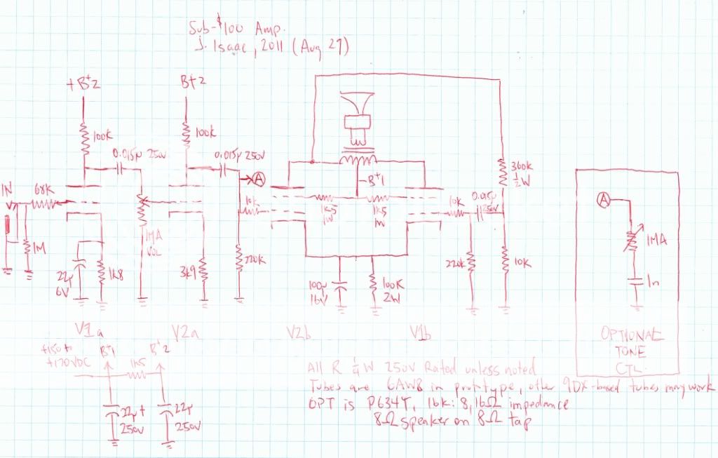
As for the stuffing... I've been heavily inspired by the good work done on the http://www.ozvalveamps.org website, especially the AVA section where they describe building an amp using off the shelf parts costing less than $200. The only thing is that every amp they have uses two or more power transformers, and that's not cheap enough for me! So I thought and searched for a way to use a single low voltage transformer for both heater and B+ supply (through a voltage multiplier). I came across the 15AF11, a tube with two nice linear triodes, a power pentode (a bit like a 50C5 only with more transconductance) and a 14.7V, 0.45A filament... two of these in series can strap across a 30V transformer, which can be quadrupled for 150V raw B+, or so the theory goes... I set to work (schematic coming - this is a gain-y creature, and it squeals a bit when maxed - this may be partly due to wire length in some places. I have to pull out my scope and go hunting.)

Image

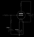
To the left is the quadrupler power supply on a salvaged piece of GPO-3... currently the caps are held down with hot glue but I will redo the whole board before mounting permanently in its final home. With the transformer shown (an overkill 80VA 27.5V toroid; I'm looking for a smaller unit for the final amp) giving 29VAC out the quadrupler does in fact produce 155V of pretty clean B+, although there is less plate current being drawn than I expected, so it may drop a bit in future.
The main board construction is primitive but stable - nails in a piece of wood for the tie points. All offboard wiring is colour-coded, thanks to the wiring harness from an old TV. One nice thing about the B+ being so low is that most of the parts can be 250V rated, which makes parts gathering easier. Barely visible between the two tube sockets is a conjunctive filter, which is needed to tame ringing on the output (again, long wires are not helping things!)

Image

The amp design has two gain stages with volume and a big-muff-style tone control, followed by a paraphase inverter - so total gain from the input jack to the output tubes is something like 6000x, or 75dB... yeah, it's got gain. It sounds fantastic when it isn't oscillating!

More details and sound clips to come, when I've got some more bugs out of it...
Vacuum tubes: now (mostly) chemical free!
User avatar
jonnyeye
 
Posts: 109
Joined: Thu Feb 12, 2009 3:04 pm
Location: Sunderland, ON

Postby Hotsauce » Wed Jul 27, 2011 11:51 pm

For your turret board, you might want to use threaded posts and binder nuts instead of solder posts. This would allow quick A/B testing without damaging leads.

John C.
User avatar
Hotsauce
 
Posts: 88
Joined: Sun Sep 21, 2008 5:56 pm
Location: Bronxville

Postby Austin Translation » Thu Jul 28, 2011 7:01 pm

Awesome I love it! Im trying to do a similar thing, but with a bogen pa chassis and supply. I have lots of 6f6 tubes so thats what I am using, its a learning experience for sure. Fun stuff!!! I would love to hear sound clips!!
User avatar
Austin Translation
 
Posts: 32
Joined: Wed Jun 29, 2011 9:57 pm

Postby jonnyeye » Fri Jul 29, 2011 1:02 am

Hotsauce wrote:For your turret board, you might want to use threaded posts and binder nuts instead of solder posts. This would allow quick A/B testing without damaging leads.

John C.

That's a pretty good idea; when I get things a little more permanent, I'll keep it in mind. For now, I wanted to hit the ground running, and you can't beat the convenience and cheapness of iron nails in a bit of scrap wood.

Austin Translation wrote:Awesome I love it! Im trying to do a similar thing, but with a bogen pa chassis and supply. I have lots of 6f6 tubes so thats what I am using, its a learning experience for sure. Fun stuff!!! I would love to hear sound clips!!

Thanks! Using a real chassis as a starting point would be my recommendation for anyone, really - this pan was a bear to drill, as the sides are not perpendicular to the base, and the size meant that I couldn't get the centre under my drill press. I have seen new pans with the sides at right angles, but they seem to be for professional baking (and they cost money! Really!)

Some more details on the amp - power is on the order of 1W, but I can't measure it precisely with the tools I have available. I did hook it up to my scope (a term I use with some hesitance, as it's a temperamental Heathkit IO-102) and found that the oscillations appear to be coming from the phase inverter, and that there is severe crossover distortion on anything but the smallest signals. More investigation is required, so the sound clips and schematic will have to wait.
Vacuum tubes: now (mostly) chemical free!
User avatar
jonnyeye
 
Posts: 109
Joined: Thu Feb 12, 2009 3:04 pm
Location: Sunderland, ON

Postby Austin Translation » Fri Jul 29, 2011 9:07 pm

I wish I had an oscilloscope. I wonder how the handheld kind measure up, I have seen them as inexpensive as $50. It would be nice to have one to learn on, especially that they can fit in a toolbox. I think some even double as a vom. I have no clue as to which brand is decent tho
User avatar
Austin Translation
 
Posts: 32
Joined: Wed Jun 29, 2011 9:57 pm

Postby Gingertube » Sun Jul 31, 2011 6:47 pm

I use handheld oscilloscopes for the day job work BUT you are not going to get anything very good for the $50 price you mentioned.
I use Hantek brand which are around X10 that price.
Rigol have some good bench top units for a similar price. Thats what I run at home for the hobby work.

For tube audio (even guitar amps) you want:
2 channel minimum
20MHz minimum analog bandwidth.
100MHz minimum digitising rate.
ability to use X10 probes so you don't overload the input (I have X10 and X100 probes for use at hiome).
Oscilloscope should be provided with X1/X10 switchable probes)
Cheers,
Ian
Gingertube
 
Posts: 245
Joined: Thu Oct 05, 2006 10:27 pm
Location: Adelaide, South Oz

Postby Casey4s » Tue Aug 02, 2011 10:14 am

A very inovative chassis design, what ever works (y)
Casey4s
 
Posts: 44
Joined: Tue Oct 05, 2010 6:36 pm
Location: Northern Virginia

Postby mesherm » Tue Aug 02, 2011 1:18 pm

As far as digital O-scopes go I upgraded from a Vellemen HPS10 to a Chinese made 2 channel Atten ADS1022C I got for about $300. It came with two 1x/10x probes and a USB connector and software for computer interface. It has a lot of very nice features for the money.
Mike's N-1 Rule: When looking for N number of components to finish a job, you have a 95% chance of only finding N-1 of them.
User avatar
mesherm
KT88
 
Posts: 1232
Joined: Fri Aug 27, 2004 10:33 pm
Location: Alvin Texas

Postby jonnyeye » Mon Aug 29, 2011 1:06 pm

Was it really over a month ago that I started this? Time flies...

I recently discovered a topic over on diyaudio (The Hundred-Buck Amp Challenge) that re-invigorated my interest in working on cheap amps. I took some time to poke about a bit to see if I could remove those pesky oscillations.

I have come to the conclusion that the 6/15AF11 and it's ilk (6BD11, 6AS11) are not suited for beginner-to-intermediate builders, especially in high-gain territory. The issue is that triode 2 and the pentode are in close physical quarters, which can lead to feedback issues from plate-to-plate capacitances. Ok, so run them so that the plates are out of phase, right? That might work, except that the pinout puts the grid of triode 2 right next to the plate of the pentode. So your wiring must be immaculate to prevent all possible positive feedback between those two tube sections. An experienced designer could probably create a PCB that minimizes the pinout problem, along with a judicious use of grid stoppers and HF rolloff. My crazy wiring to a wooden board with slightly too long wires just doesn't cut it... It's a shame too, because the 6AF11 has two very nice triodes (triode 1 is a kissing cousin to half a 6SL7, and triode 2 is like a much more linear 12AV7) that it's a shame to have to reject the tube for user-unfriendliness.

Anyway, I removed that amp from the chassis and started working on something a bit less gainy, instead using 6AW8 tubes. These are nice members of a class of triode-pentode tubes with the basing 9DX (of which there are probably two dozen!), many of which feature high-gain triodes and various flavours of quality pentodes. The 6AW8 is a little unusual among these in that the pentode is only rated for 3W dissipation (most of them are rated for 5W), so I figured it was a good place to start. It wasn't at all because I had two pairs in my junkbox, so I could set to work without having to wait for the mail ;).

The amp that I built thus far is mostly quite orthodox - 150-170V B+ (using a bench supply, which also lets me watch current draw), standard topology with two CC gain stages driving a self-split pair - the difference is that I am using a paraphase self-split output, where the drive signal for the second output tube is derived from the plate of the first output tube. I came up with this independently a while back, but I've seen other implementations of it before. (see, for instance, the output of 2.1 on http://www.dmitrynizh.com/submini-vibro-reverb.htm). The biggest advantage to this kind of self-split is that you retain all the gain and power output (well, most anyway) of having a traditional phase inverter without having to add another tube section to do it. The biggest disadvantage is an increase in 2nd harmonic distortion - wait, no, for guitar that's another advantage!

As built thus far (no pictures or schematic, yet - I'm going to move to a more permanent building/tweaking phase of this in the next couple of days, anyway) the amp has a nice breakup characteristic, and gets plenty loud into an old Jensen C8R that I have. The only caveat is that a transformer with a 16k primary is required for these tubes - I got one for $9 from Newark a while back (it's a 100V line transformer, model P634T), but I can't seem to find the version I got on their site anymore.
Vacuum tubes: now (mostly) chemical free!
User avatar
jonnyeye
 
Posts: 109
Joined: Thu Feb 12, 2009 3:04 pm
Location: Sunderland, ON

Postby jonnyeye » Tue Aug 30, 2011 9:14 am

Schematic for the new amp, as built (roughly). Note that the 360k 1/2W must have a rating of 350V minimum (it sees about 300V across it on signal peaks)
Image

Permanent build will be in the next couple of days as I have more free time (I'm in an end of the month crunch!)
Vacuum tubes: now (mostly) chemical free!
User avatar
jonnyeye
 
Posts: 109
Joined: Thu Feb 12, 2009 3:04 pm
Location: Sunderland, ON


Return to guitar amps

Who is online

Users browsing this forum: No registered users and 6 guests

cron