I De Tweeded my 5F6A Bassman! !

a fine line between stupid and clever

I De Tweeded my 5F6A Bassman! !

Postby Casey4s » Sun Feb 13, 2011 3:59 pm

I got snowed in Dec. 24, and have only been able to get out 6 times until this week. (Not so much snow here but I am 63 with a 300 foot uphill driveway and a bad ticker LOL)

So I went a little nuts looking for something to do, so I tore into the 5F6A Tweed Bassman clone I scratch built in 1998/99. When I got finished it turned into a killer sounding combo amp but all the "Tweed" is gone. I am not quite sure what to call this amp now so I just refer to it as my "DeTweed" combo amp.

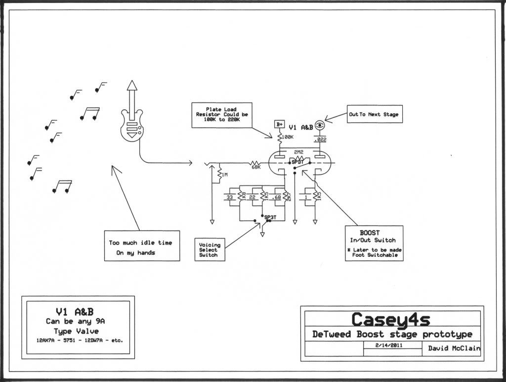
I started at the first stage and gave myself 3 different switchable voices (load lines) to choose from.

Then I added the Weber Active Tone Stack in place of the usual drain to ground tone circuits from Fender, Vox, Marshall etc. Wow what an impact it has on my over all tone. The midrange is the most "dynamic" of the three controls in my application. I am still tweaking this a bit.

I changed the Presence circuit from the Tweed style to the 6G6 style and that made a little improvement in it's performance.

I left the PI alone, but I added a Post PI Master Volume control to the power amp making the original volume control the master GAIN control. This improvement alone is well worth a few dollars in parts and little time it took to do this mod.

Then I went back and orphaned V1-B to use later for an upcomming modification. Either as a reverb recovery OR as a Boost stage to V1-A

I had to stiffen up the power filtering a bit, and I am waiting on parts for the final version, it's a bit "stiff" right now. At the moment I am at 80 - (choke) 40 - 20 - 16 I want to end up with 60 - (choke) - 40 - 20 - 8. I ran the Duncan simulator to choose this combination.

I added a Hum Balance pot which eliminated the little bit of heater noise I did have. Another good choice in my case.

As long as I was playing around in the power supply I decided to add a Solid State - Tube rectifier switch just for grins and giggles. A simple no brainer install and was dirt cheap to do. I get about a 40VDC gain at the first filter.

While I was doing all this over a several week period I changed all of the signal and coupling caps. In the Active Tone stack I used the AES foil in oil MOD capacitors. The .1 coupling caps are paper in oil (PIO) great big orang ones but I don't know the (US) brand. The remaining two .022 caps are those Russian PIO caps that are flooding the market at the moment.

I forgot to mention in the beginning of this post that when I originally built my 5F6A I built it with a 4x6V6 power amp instead of 2x5881/6L6. I also added 1.5K swamper resistors and 1 ohm bias test resistors to the power amp.

I completely re-tubed the amp from preamp to rectifier with all brand new NOS tubes.


I know everyone here already knows what a 5F6A Tweed bassman schematic looks like but... http://www.el34world.com/charts/Schemat ... _schem.pdf


So here is what my severely "De Tweeded" Bassman? looks like on paper. This is "As Built"

Image

Image


Any comments, questions, remarks, observations, wise cracks?
Casey4s
 
Posts: 44
Joined: Tue Oct 05, 2010 6:36 pm
Location: Northern Virginia

Postby Greg Smith » Mon Feb 14, 2011 10:54 am

Casey,

Your preamp topology is interesting. I like the idea of the switchable voicing on the first stage cathode. Not many builders have gone down the route of active eq., but the idea probably deserves more attention/experimentation than it gets.

A bit of concern over your PPIMV design: you have your DC bias supply connected directly to the pots. DC on pots tends to lead to scratchiness in the output when the pot is adjusted. Also, It seems as if the bias voltage seen by the output tube grids would change as the MV is adjusted. I would suggest that you isolate the PPIMV from the output tube grids (and the bias voltage) with a second pair of coupling capacitors. Adding a PPIMV is a great idea IMO, but it's much easier to implement on cathode-biased output stages.

Cheers,
gs.
User avatar
Greg Smith
 
Posts: 30
Joined: Sun Dec 07, 2008 11:48 am
Location: Ottawa, Canada

Postby Hotsauce » Mon Feb 14, 2011 1:19 pm

Is there a way to make it continuously variable?

Would it work to have a fixed low value cap, like the .68, and a pot in series with a larger cap to feed in more?(the larger cap and pot paralel to the smaller cap)

John C.
User avatar
Hotsauce
 
Posts: 88
Joined: Sun Sep 21, 2008 5:56 pm
Location: Bronxville

Postby Geek » Mon Feb 14, 2011 6:13 pm

Greg Smith wrote:Your preamp topology is interesting.


I recognize it - Peavey ;)

My two-bits:

- Forget the hum balance and just lift the heaters +50V off ground with a voltage divider from B+. That will also act as a safety bleeder.

- The .1uF coupling caps to the output tubes... WAY too big. Try .022

- Put the master volume before the phase splitter.

- 80 or 60uF is far too big. 47uF max on a 5U4 and if you roll rectifiers, better make it a 22uF.

- Fuse goes inline the line side before the switch always for safety.

- You have a primary CT that's grounded... lose that.

Cheers!
-= Gregg =-
Fine wine comes in glass bottles, not plastic sacks. Therefore the finer electrons are also found in glass bottles.
User avatar
Geek
KT88
 
Posts: 3585
Joined: Sun Oct 21, 2007 3:01 am
Location: Chilliwack, British Columbia

Postby Casey4s » Tue Feb 15, 2011 6:15 pm

Greg:

What do you suggest as a cap value for the new coupling caps? I have indeed been having some problems with unstable bias and you just gave me the answer I have been looking for. (I Think) Because that makes perfect sense.


PS:

My DSL modem died yesterday and I am at the public library answering this, so my replies will be few until Friday or so.
Casey4s
 
Posts: 44
Joined: Tue Oct 05, 2010 6:36 pm
Location: Northern Virginia

Postby EWBrown » Tue Feb 15, 2011 6:27 pm

The coupling caps between the LTPI and the 6V6s should be 0.02 or 0.022 uF, (and no higher than 0.047 uF, to accomodate the paralleled 6V6GTs) as used further upstream in your design.

The 0.1 uF coupling caps will pass excessively low frequency, which is not a problem with HIFI audio, but with a guitar amp, the lower E string is usually tuned to around 82 HZ, and on a bass, 41 Hz, though the five or six string basses may go somewhat lower starting frequency, if they start at D or lower..

The 0.1 uF caps in the "lower" half of the LTPI, and the presence control are OK, as they aren't directly carrying the audio signal, they control the negative feedback, and act somewhat to bypass the lower grid to signal ground.

/ed B
Real Radios Glow in the Dark
User avatar
EWBrown
Insulator & Iron Magnate
 
Posts: 6389
Joined: Wed Mar 19, 2003 6:03 am
Location: Now located in Clay County, NC !

Postby Hotsauce » Thu Feb 17, 2011 8:56 am

Would a pot to fade between 2 caps work as a variable cap on the input tube?

John C.
User avatar
Hotsauce
 
Posts: 88
Joined: Sun Sep 21, 2008 5:56 pm
Location: Bronxville

Postby Geek » Thu Feb 17, 2011 5:09 pm

Casey4s wrote:My DSL modem died yesterday and I am at the public library answering this, so my replies will be few until Friday or so.


Oh, that sucks! (sick)

Ed took care of the question. He knows a lot about a lot ;)

Cheers!
-= Gregg =-
Fine wine comes in glass bottles, not plastic sacks. Therefore the finer electrons are also found in glass bottles.
User avatar
Geek
KT88
 
Posts: 3585
Joined: Sun Oct 21, 2007 3:01 am
Location: Chilliwack, British Columbia

Postby Casey4s » Fri Feb 18, 2011 2:55 pm

EWBrown wrote:The coupling caps between the LTPI and the 6V6s should be 0.02 or 0.022 uF, (and no higher than 0.047 uF, to accomodate the paralleled 6V6GTs) as used further upstream in your design.

The 0.1 uF coupling caps will pass excessively low frequency, which is not a problem with HIFI audio, but with a guitar amp, the lower E string is usually tuned to around 82 HZ, and on a bass, 41 Hz, though the five or six string basses may go somewhat lower starting frequency, if they start at D or lower..

The 0.1 uF caps in the "lower" half of the LTPI, and the presence control are OK, as they aren't directly carrying the audio signal, they control the negative feedback, and act somewhat to bypass the lower grid to signal ground.


/ed B


Thanks ED, and every one who commented. I got good input.

I added the extra two .022 caps and changed the ther two .1 to .022 two days ago. I had wondered about the caps being .1 when I most often see .01 or .02 in those places.

I also went back to two 100 ohm resistors to ground my heaters. The balance pot seems to make the PT run hot.

I also changed out my power supply filters to reflect, 40, C. 40, 20, 8 to make life easier for the tube rectifier.

My fuse was wired correct but reflected in the drawing incorrectly.

I have new drawings to post as soon as I can get out of the public LIBRARY!
Casey4s
 
Posts: 44
Joined: Tue Oct 05, 2010 6:36 pm
Location: Northern Virginia

Postby Casey4s » Mon Feb 21, 2011 4:41 pm

I finally got back online this afternoon, (after 8 days Verizon) so I can post the revised schematics and a drawing of my "proposed" Boost.

Revision I is the current "as built".


Revision I
Image

Revision I
Image


Image


Obviously I got bored without the internet so I played with the CAD software some on a couple of the draings LOL....[/i]
Casey4s
 
Posts: 44
Joined: Tue Oct 05, 2010 6:36 pm
Location: Northern Virginia

Postby Greg Smith » Tue Feb 22, 2011 12:04 pm

Casey, good choice of values for the coupling caps, but you still have a problem with your bias supply - quite a serious problem actually. As currently wired, the second pair of coupling caps ISOLATES the bias supply from the tube grids. So, right now, your output stage is not biased at all!

Have you noticed the output tubes red-plating? They must be drawing a lot of current.

You need to connect the bias supply, through a pair of 100k resistors, to the output tube grid resistors (i.e. to the other side of the two new .022 uf coupling caps).

Second, connect the bottom terminal of each half of the master volume pot to ground (they used to be connected to the bias supply).

Hope that makes sense.

Greg
User avatar
Greg Smith
 
Posts: 30
Joined: Sun Dec 07, 2008 11:48 am
Location: Ottawa, Canada

Postby Casey4s » Tue Feb 22, 2011 1:25 pm

Greg Smith wrote:Casey, good choice of values for the coupling caps, but you still have a problem with your bias supply - quite a serious problem actually. As currently wired, the second pair of coupling caps ISOLATES the bias supply from the tube grids. So, right now, your output stage is not biased at all!

Have you noticed the output tubes red-plating? They must be drawing a lot of current.

You need to connect the bias supply, through a pair of 100k resistors, to the output tube grid resistors (i.e. to the other side of the two new .022 uf coupling caps).

Second, connect the bottom terminal of each half of the master volume pot to ground (they used to be connected to the bias supply).

Hope that makes sense.

Greg


Thanks Greg I appreciate your help.

I did in fact have a problem with the bias and I couldn't understand what was causing it.

Do I need to put the two 100K resistors between my new .022 cap and my 1K5 swampers?

OR

Between the pot and the new caps?

You lost me on the grounded pot lug altogether.

I had my PT overheat recently and must have been because of the biasing problem. I was also getting a harsh roaring hum if I turned the MV past 75% which indicated undebiasing. You have given me a great deal of insight here. I was on the right track but just couldn'g pin point the source.

Before I do anything, I'll redraw it for you to check.
Casey4s
 
Posts: 44
Joined: Tue Oct 05, 2010 6:36 pm
Location: Northern Virginia

Postby Casey4s » Tue Feb 22, 2011 1:52 pm

Ok I am going to post my interpertation of your instructions about the 100K resistors.

I don't understand the pot instructions at all. If I connect the pot post that is currently on the bias -voltage to ground i am confused how the bias then would be wired...???


Thanks for all the help

Image
Casey4s
 
Posts: 44
Joined: Tue Oct 05, 2010 6:36 pm
Location: Northern Virginia

Postby Casey4s » Tue Feb 22, 2011 2:28 pm

Here's what the instructions sound like, but of course that's not right...LOL

I have misunderstood somehow...


Image
Casey4s
 
Posts: 44
Joined: Tue Oct 05, 2010 6:36 pm
Location: Northern Virginia

Postby Casey4s » Tue Feb 22, 2011 3:07 pm

How about this?


Image
Casey4s
 
Posts: 44
Joined: Tue Oct 05, 2010 6:36 pm
Location: Northern Virginia

Next

Return to guitar amps

Who is online

Users browsing this forum: No registered users and 6 guests