Champzilla: a Champ amp on steroids, AKA The Uglytron

a fine line between stupid and clever

Champzilla: a Champ amp on steroids, AKA The Uglytron

Postby EWBrown » Fri Jan 21, 2011 9:03 pm

Image

Image

Just like with a Klein Bottle, its inside is also its outside :/ ;) (lol)

Image
УНИВЕРСАЛ ТЕХНО-КОНТРОЛЬ

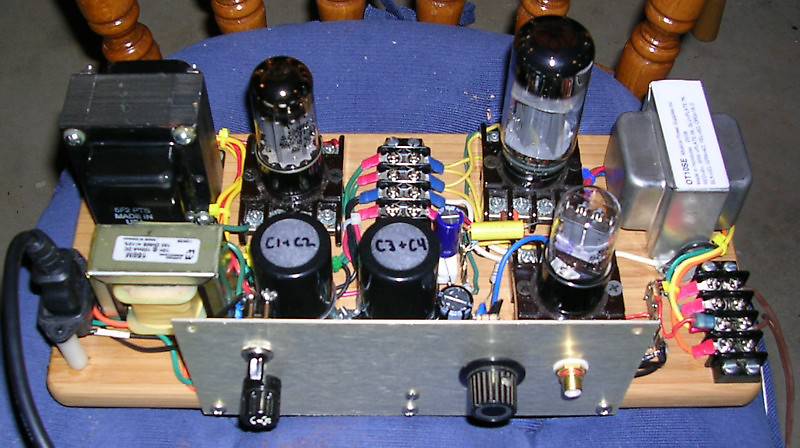
I decided to throw together a "breadboard" version of an all-octal Champ amp, literally on an unused 13.5 inch long bamboo cutting board, which I bought a couple of these at a "Dollar Store" last year, for just a purpose. I took a leisurely pace with this over Thursday and Friday afternoone & early evenings. With my still-fuzzy vision, I just had to be a bit more careful and patient than usual, so no mad rush to git 'r' done...

I used three octal relay sockets, and for the PSU, one of the Triode Electronics 5F2 power trannnies, and a Hammond 158M 10H, 100 mA choke, which is not standard Champ-issue ;) OPT is one of the 10 watt SE OPTs from Musical Power Supply on e-bay. Very similar to a 125ESE but cheaper, this particular one was made in Honduras (and not China) .

Yeah, it's kinda ugly, but in a cute sort of way ;) I'll post a photo or two soon...

Definitely not suitable for use around toddlers, curious pets, or folks who have an insatiable need to "look" with their fingers, since there is plenty of exposed HV AC and DC voltages lurking about. Not just a nasty shock, but potentially lethal. (666)

The circuit is classic basic "Champ" for all resistor values, but with the exception of using a 6SL7 instead of 12AX7. and the added choke which gives me a C-L-C-R-C-R-C PSU string. Caps are two of the J/J 32 + 32 uF / 525 V units, and an added 22 uF / 450V cap at the end of the string.
I have only the volume ontrol, and no tone stack, just to keep it relatively simple for now..

I doubled up the capacitance on the B+ to the OPT section for 64 UF, the first and third sections are 32 uF. Not as "saggy" B+ as the vintage 8 or 10 uF caps, as I wanted to have a little more available DC stored-charge power.

With the standard tube lineup of 5Y3GT, 6SL7 and J/J 6V6S, it preformed as expected, nothing really special.

What did truly surprise me was that it was totally hum-free, I figured with a wooden base, and the relay sockets, and lots of "flying" wire leads, that it would hummmm like a cheap electric shaver, but it did not :)) [:)

Since the PT has enough spare VA capability, I wondered what would happen, if I swapped out the rectifier and output tube, and put in a Sovtek 5AR4 and a Russian 6L6WGC / 5881.

With the 5AR4 I now have 395V B+ to the OPT and 31V cathode bias across the 500 ohm 5W cathode resistor, for 62 mA cathode current.

With the 5Y3GT and 6V6, I had 365 VDC B+ and 45 mA (22.5V) across the 500 ohm cathode resistor, and about 208VDC plate voltage on both 6SL7 sections. The PD on the 6V6 was about 15W, just a tad above tie normal PD rating, but not enough to red-plate it.

This gives me about 22-23 W of plate dissipation which is safely below the 30W max rating.

The 6SL7 driver stages also have a bit more "juice" and are running around 1.4 mA plate current, and 227V on the plates.

All I can say, is it has a LOT more power, and better overall response, but since I am using just an old cheap 8 ohm bookshelf speaker, I can't really say how it would sound through a proper guitar amp speaker mounted in a proper cab.

Next is to obtain an 8 or 10 inch MI speaker and cobble together a reasonable facsimile of a Champ speaker box, and give it a more proper listening test. And then to put it all together on a proper metal chassis, once I iron out any potential "bugs" that I may discover with use.

I'll preserve the "wooden wonder" as it is very handy for prototyping and testing new ideas, and I have duplicate parts for a more permanent build..

I wouldn't recommend taking a standard Fender Champ (or a clone) and just doing the 5AR4 & 6L6WGC tube swap, as it may then become a smoke-emitting or fire-belching "Chump" in rather short order.

The MPS OPT is fairly hefty, more so than the normal "dainty" Champ OPTs, (NEVER do this to a TF103) and it can readily handle the extra DC current coursing through its primary, and the Triode power trannie has extra VA capability than the original "just good enough" PT.

Per favore, no rompere mi coglioni about the RCA jack - I couldn't find my small stash of 1/4 inch shorting phone jacks at the time. I later did find four, but none with the "shorting" contact, so the RCA remains for now...

Update: I replaced the RCA jack with a 1/4 inch jack, so it is now completely "legitimate" (b)

/ed B
Last edited by EWBrown on Mon Jun 09, 2014 10:53 am, edited 8 times in total.
Real Radios Glow in the Dark
User avatar
EWBrown
Insulator & Iron Magnate
 
Posts: 6389
Joined: Wed Mar 19, 2003 6:03 am
Location: Now located in Clay County, NC !

Postby Geek » Sat Jan 22, 2011 3:55 am

Sounds like something George (Tubelab.com) would cobble ;)

Pics?

Cheers!
-= Gregg =-
Fine wine comes in glass bottles, not plastic sacks. Therefore the finer electrons are also found in glass bottles.
User avatar
Geek
KT88
 
Posts: 3585
Joined: Sun Oct 21, 2007 3:01 am
Location: Chilliwack, British Columbia

Postby EWBrown » Sat Jan 22, 2011 5:41 pm

It was all done in the spirit of Tubelab George, but without the red plate tubular death testing (666) (666) (666)

I'll eventually haveImage pics of the Wooden Wonder, stay tuned...

/ed B
Last edited by EWBrown on Mon Feb 14, 2011 10:14 pm, edited 1 time in total.
Real Radios Glow in the Dark
User avatar
EWBrown
Insulator & Iron Magnate
 
Posts: 6389
Joined: Wed Mar 19, 2003 6:03 am
Location: Now located in Clay County, NC !

Postby dhuebert » Tue Jan 25, 2011 9:27 am

As you know I have been prototyping on wooden boards for years. Sometimes they buzz and sometimes not. My distortion box buzzed so hard it was impossible to tell if it was working! Pictures or it didn't happen.
Don
User avatar
dhuebert
KT88
 
Posts: 820
Joined: Thu May 01, 2003 9:26 am
Location: Winnipeg Manitoba Canada

Postby EWBrown » Tue Jan 25, 2011 1:29 pm

I'd done prototyping on wooden boards back in the '60s but it was all radio or low-powered transmitter circuitry, not anything truly audio-specific. Some battery powered, some AC lined powered - I did get my fair share of AC nips and bites from those :'(

That format was the standard fare for DIY builders back in the 1920s to the 1940s, my dad showed me the basics of building up and getting a real "breadboard" to work properly. It even worked for Atwater-Kent with their Model 10 series:

Image

It is beastly hard to get a really high gain circuit to behave on a wooden board, and the hyperactive high gm tubes can be a real challenge, as they just love to oscillate wildly, given half a chance. Even the guitar amp squeals if I turn it up all the way without shorting or loading the input jack.

Over more recent times I have built up test amps on wood, as well as several "generic" PSUs of various voltages, which I still have available for use.


Image

See, it really happened ;) (lol) O:) it's so nice, I even posted it twice [:) the two big electrolytics marked "C1+C2 and C3+C4" are J/J 32+32 uF.

Oh, yeah, after the photo was taken, I changed out the RCA input jack with a 1/2 inch "phone" jack. Now it's Politikally Korrekt, Komrades >:o

/ed B
Last edited by EWBrown on Tue Nov 01, 2011 7:33 am, edited 3 times in total.
Real Radios Glow in the Dark
User avatar
EWBrown
Insulator & Iron Magnate
 
Posts: 6389
Joined: Wed Mar 19, 2003 6:03 am
Location: Now located in Clay County, NC !

Uglytron II / Champzilla II

Postby EWBrown » Tue Jun 07, 2011 6:43 pm

Uglytron II will be arising soon... I was recently given a very clean condition Knight KN3210 tube PA amp, as well as seven NOS 8 inch ceiling mount speakers, complete with 70V line matching trannies. The amp's OPT can handle 4, 8, 16 ohms and 25 or 70V line distribution.

The amp is the best part, the speakers are just a "bonus".

The tube lineup is 12AX7, 6L6GC and 6CA4 rectifier. It claims to be a ten watt single ended PA amp, and has two "auxillary" line inputs and a microphone input, probably for a crystal mike. I may sub an octal rectifier for the 6CA4, depends if it is still good or if it is getting weak and lazy (kinda like me, lately) ;) (lol)

I suspect its basic circuitry isn't a whole lot different than the 8W 6L6GC SE amp in the back of the RCA tube manual. Simple enough to trace it out and "reverse engineer"...

Well, with a bit of re-designing it can become another Champzilla "Uglytron", but this time, mounted in a nice steel chassis and cabinet.

I dunno if the 8 inch (8 ohms) speakers would be any good for use as guitar speakers, but for the price (free) it mighe be worth trying out, either as a single, a pair or a 2X2 series parallel array.

Free is ALWAYS good :)) [:)

/ed B

Image
УНИВЕРСАЛ ТЕХНО-КОНТРОЛЬ
Last edited by EWBrown on Mon Jun 09, 2014 10:57 am, edited 6 times in total.
Real Radios Glow in the Dark
User avatar
EWBrown
Insulator & Iron Magnate
 
Posts: 6389
Joined: Wed Mar 19, 2003 6:03 am
Location: Now located in Clay County, NC !

Its' ALIVE!!! It's ALIVE !!!!

Postby EWBrown » Wed Jun 08, 2011 6:15 pm

I carefully re-formed the quad section can cap (it really needed it) with 400VDC for the HV sections and 25V for the cathode bypass, and then powered it up, it works like brand new, no noise, no hum, no buzz, no ripple and no scratchy pots :)) [:)

The actual operating B+ is approximately 385V, with 55 mA cathode current on the 6L6GC, with 27.5VDC across the 500 ohm, 5W WW resistor. All of the tubes appear to be operating within "new" specifications. [:)

The circuitry is absurdly simple, and reworking the 12AX7 section to become a Champzilla, and adding a 1/4 inch phone jack input would be an easy afternoon's work.

Take out and replace the ceramic disc caps, and put in newer resistors to replace all of the 50 year old carbon comp 10% ersistors (most of which are amazingly still within tolerance). Next rainy day project...

/ed B
Real Radios Glow in the Dark
User avatar
EWBrown
Insulator & Iron Magnate
 
Posts: 6389
Joined: Wed Mar 19, 2003 6:03 am
Location: Now located in Clay County, NC !

Postby dhuebert » Thu Jun 09, 2011 8:35 am

Why would you replace the ceramic caps? This is a guitar amp and those things supposedly make even harmonics, just what you want!

Don
User avatar
dhuebert
KT88
 
Posts: 820
Joined: Thu May 01, 2003 9:26 am
Location: Winnipeg Manitoba Canada

Postby mashaffer » Thu Jun 09, 2011 6:16 pm

Nice breadboard setup. Love those sockets. What we need are some 12 pin and 9 pin compactron versions of those sockets along with miniture 9 pin versions. Would be the cat's meow.

mike
mashaffer
 
Posts: 34
Joined: Wed May 28, 2008 5:02 pm

Postby EWBrown » Sat Jun 11, 2011 8:05 pm

I ran the amp today with a CD player, for a few hours, and the ceramic disc caps really don't sound too bad. There is a slightly noticeable sharpness with them, but it is not objectionable, and that should be good for guitar amp usage.

It also has a somewhat weird NFB loop scheme, which comes off the 4 ohm OPT tap, through a 10 meg resistor and back into the mic stage's input grid. which I would take out, or reconfigure to a more "standard" design.

So, at least for now (or the next really rainy day) I'll just reconfigure the 12AX7 section to that of the champ(zilla) with 1.5K RK and 100K RPs and take out the intermediate line input "mixer" which is a unique center tapped, log and anti-log pot pot, and a couple of 470K resistors, bypassed with 0.01 uF ceramic discs, which also acts as a form of line input selector.

The tone control just throws another 0.1 uF ceramic disk, and 500K pot across the 6L6GC's input grid. Easy enough to leave in, or defeat, as sounds best.

/ed B
Real Radios Glow in the Dark
User avatar
EWBrown
Insulator & Iron Magnate
 
Posts: 6389
Joined: Wed Mar 19, 2003 6:03 am
Location: Now located in Clay County, NC !


Return to guitar amps

Who is online

Users browsing this forum: No registered users and 12 guests

cron