Page 1 of 1

Stereo 70 Mechanical Drawings

PostPosted: Wed Oct 24, 2012 4:16 pm
by kt88pppamp
Does anyone have mechanical drawings for a ST70 chassis? I need at least the:

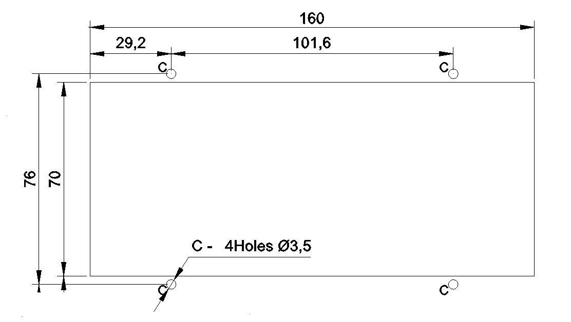
- Driver board dimensions and mounting hole spacing.

- Mounting hole spacing for the output transformers.

I am making my own mod for a ST-70 and will not include the 5AR4 tube and stock bias circuitry. Anyone have any ideas what do to with the holes. I feel like I need to use them for something.

PostPosted: Wed Oct 24, 2012 4:26 pm
by burnedfingers
If your not using the 5Ar4 then you must be using diodes and what nicer way of using the hole than putting a damper diode tube in its place. The bias pot holes can be plugged by using either plastic or chrome plugs that are available at most hardware stores.

PostPosted: Wed Oct 24, 2012 5:07 pm
by kt88pppamp
Will this part fit the socket spacing if I were to mount a multisection cap?

http://www.tubesandmore.com/products/S-H120M

PostPosted: Thu Oct 25, 2012 7:27 am
by tomlang
Edited to say that is a better drawing below than I have...

PostPosted: Fri Oct 26, 2012 12:05 pm
by Quad
Here's the drawing for the board ... all dimensions in mm
(image is from diyaudio - hope it shows up)

Image

PostPosted: Tue Oct 30, 2012 5:30 pm
by kt88pppamp
The image did show up. I am making my ST70 driver board 169mm x 85mm. Will this work or are these dimensions too close to the edge or the EL34 sockets.