Uses for an old quad cap

knowledge base for the classic Dynaco ST70

Uses for an old quad cap

Postby TerrySmith » Sun Feb 13, 2011 3:25 pm

I came up with an idea for the quad cap when a cap board is installed. Why not restuff it and use it as a reinforcement!

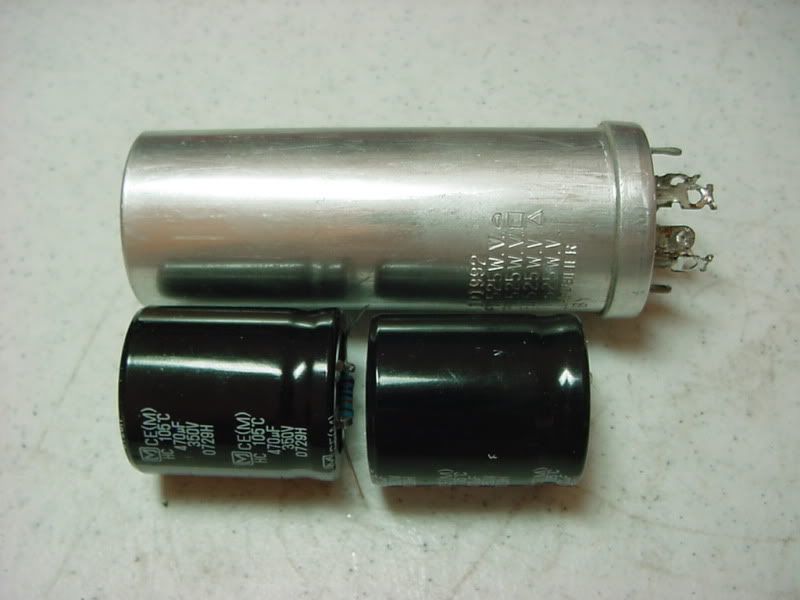
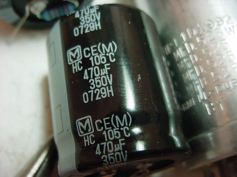
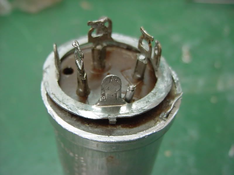
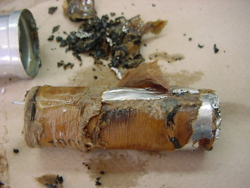
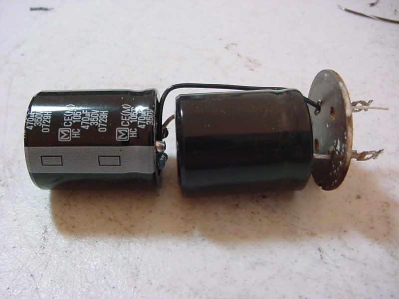
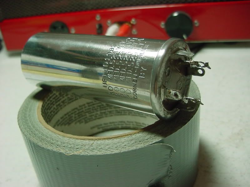
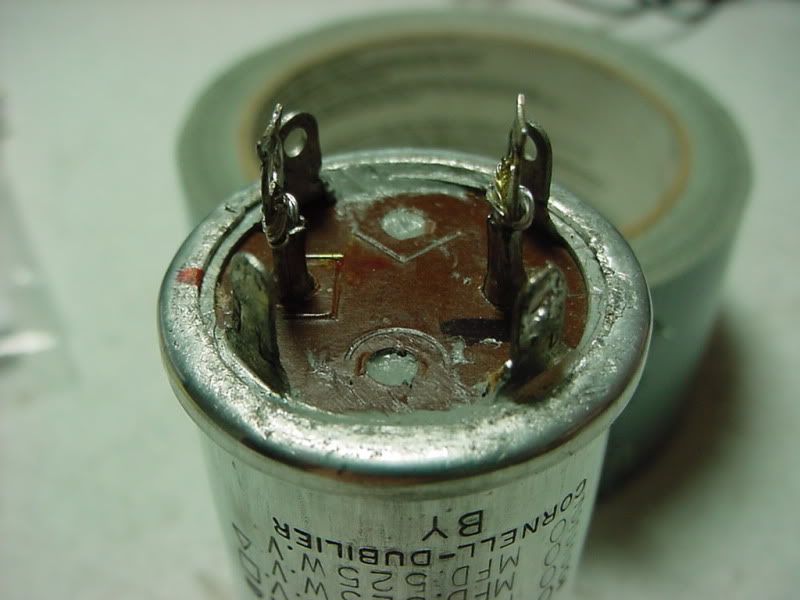
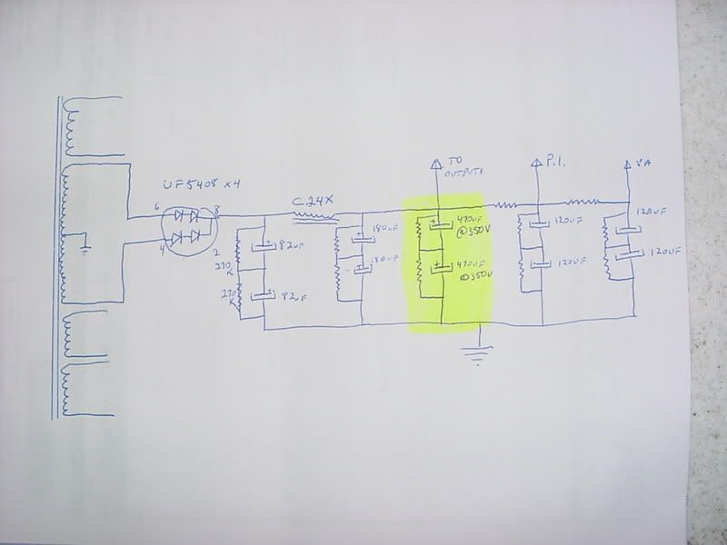
This cap was removed from another Dyna project in good physical condition. I ground off the lower lip and removed the guts, then stuffed two 470uf @ 350v Panasonic caps in series and 270k bleeders. Then reinstalled just the terminal plate and retainer ring and carefully crimped it shut. This will net a single 235uf @ 700v cap to parallel with the second caps on the cap board. Caps on the board are 2x 82uf@400v, 180uf@350v, 4x 120@350v.

The power supply ends up being 41uf@800v - choke - 325uf@700v - 6.8k - 60uf@700v - 22k - 60uf@700v. Now I can use SS diodes and not have to worry about it blowing up and also use a 5AR4 if I wish.

Image

Image

Image

Image

Image

Image

Image
T. Smith
User avatar
TerrySmith
KT88
 
Posts: 973
Joined: Sat Jan 31, 2004 12:51 pm
Location: Maryville TN

Postby TomMcNally » Sun Feb 13, 2011 5:32 pm

I usually just replace the foil, Reynolds Wrap works fine.

Image
User avatar
TomMcNally
Darling du Jour
 
Posts: 2729
Joined: Sat Nov 19, 2005 2:19 pm
Location: Northfield, NJ

Postby Shannon Parks » Mon Feb 14, 2011 6:10 am

So if you remove the bottom metal ring it will all slide out? Maybe a little heat would help? I made a horrible mess years ago when I attempted this with a large Unibit. :))

Shannon
User avatar
Shannon Parks
Site Admin
 
Posts: 3764
Joined: Tue Mar 18, 2003 5:40 pm
Location: Poulsbo, Washington

Postby TerrySmith » Mon Feb 14, 2011 8:48 am

Once you have the retainer ring, terminal plate and spacers out the guts are next. This one was shriveld up and had 1/4" space around it so I just wiggled it right out. Usually they are set in tar, then I soak it in hot water and it will slide out.

Make sure you do this outside as it is messy and STINKS!
T. Smith
User avatar
TerrySmith
KT88
 
Posts: 973
Joined: Sat Jan 31, 2004 12:51 pm
Location: Maryville TN

Postby highflyin9 » Thu Feb 17, 2011 12:44 pm

Wow, nice work! Was it difficult to re-bevel the edge once everything was put back together?
My DIY Electronics Blog: DIYAudioBlog.com
User avatar
highflyin9
 
Posts: 119
Joined: Tue Jul 27, 2010 7:42 pm
Location: East Coast

Postby lth1 » Thu Feb 17, 2011 3:32 pm

Instead of using a grinder I use a lathe, much quicker and neater, also use a lathe to remove the metal shield on tubes like the C3m.

Lee Hankins
lth1
 
Posts: 109
Joined: Sun Mar 21, 2004 12:29 am
Location: "End of the Road" Homer, Alaska

Postby TerrySmith » Thu Feb 17, 2011 11:08 pm

The trick to re-crimping it is not to fold it all at once, just a little, do one side then the opposite and keep going around until its done. Then I took a large 1/2" drive socket and hammer to finish flattening it.
T. Smith
User avatar
TerrySmith
KT88
 
Posts: 973
Joined: Sat Jan 31, 2004 12:51 pm
Location: Maryville TN

Postby burnedfingers » Fri Feb 18, 2011 5:18 am

A lathe is nice but some don't own their own.

Nice little trick that the old radio repairers have used for years. It keeps the stock look and gives new internals.
burnedfingers
KT88
 
Posts: 640
Joined: Mon Sep 05, 2005 6:38 am

Postby lth1 » Fri Feb 18, 2011 11:10 pm

6bg6ga,

I am quite aware that most people on this board do not own a lathe, but some do, and others have access to a lathe or machine shop. I was only pointing out that there are other and neater ways to cut open the capacitor, and those with lathes may not have considered using one to open capacitors and metal clad tubes.

Cordially,
Lee Hankins
lth1
 
Posts: 109
Joined: Sun Mar 21, 2004 12:29 am
Location: "End of the Road" Homer, Alaska

Re: Uses for an old quad cap

Postby dcriner » Sat Feb 19, 2011 3:22 pm

TerrySmith wrote:I came up with an idea for the quad cap when a cap board is installed. Why not restuff it and use it as a reinforcement!
What do you mean by "reinforcement"? If you're thinking of paralleling it with you cap board, don't.
Doug Criner
dcriner
KT88
 
Posts: 309
Joined: Mon Oct 23, 2006 4:19 pm
Location: Illinois

Postby TerrySmith » Sat Feb 19, 2011 3:55 pm

I plan to parallel the caps after the choke so why not use it? Also this amp will have a CL-50 inrush limiter and SS diodes (UF5408's) hidden in a metal tube shell for everyday use.

Got the idea from Bob Latino where he does this on his ST-120 kits, I'm doing the same thing except hiding the caps inside the old can.
T. Smith
User avatar
TerrySmith
KT88
 
Posts: 973
Joined: Sat Jan 31, 2004 12:51 pm
Location: Maryville TN

Postby dcriner » Sat Feb 19, 2011 6:06 pm

TerrySmith wrote:I plan to parallel the caps after the choke so why not use it? Also this amp will have a CL-50 inrush limiter and SS diodes (UF5408's) hidden in a metal tube shell for everyday use.
OK, that sounds like a plan. However, I wouldn't use a CL-50, which is rated at 5A - it won't heat up enough to effectively reduce the steady-state resistance with an ST-70, so you will get too much voltage drop. I would use a CL-80 (rated at 3A) or a CL-90 (rated at 2A).

The rated power consumption of the -120 is more than an ST-70 - so you need to use a smaller current limiter.

The replacement caps you're wiring into the can are rated 350V. That's too skimpy for the ST-70 filter caps, even after the choke. With silicon diodes, the B+ voltages will be higher than in the stock ST-70 (unless you add a ballast resistor).

I'm not sure what you are getting at by "everyday use."
Doug Criner
dcriner
KT88
 
Posts: 309
Joined: Mon Oct 23, 2006 4:19 pm
Location: Illinois

Postby DeathRex » Sat Feb 19, 2011 8:03 pm

Amazing as it sounds, a large group of the CL thermistors will have about the same resistance for a given current. GE has a chart and formula to use to figure resistance at X current with CLXX. I think a ST-70 uses about 1.75 amps. A CL80 will have 0.98 ohms at 1.75 amps. And a CL50 will have 0.68 ohms at 1.75 amps. A CL190 will have 0.62 ohms at 1.75 amps. A CL110 will have a resistance of 0.4 ohms at 1.75 amps and heat up faster.
At first I wanted to be a ET. Now I are one.
User avatar
DeathRex
KT88
 
Posts: 1014
Joined: Wed Nov 18, 2009 8:13 pm
Location: Cortez, CO

Postby TerrySmith » Sat Feb 19, 2011 9:19 pm

Just to clear up any confusion here's a crudely drawn schematic of my power supply plan. All bleeder resistors are 270k. All electrolytic caps are rated @ 350v, connected in series the rating totals 700v which should be plenty for SS rectification. The highlighted part is what I stuffed in the old cap can. The rest of it is on the cap-board.

Image
T. Smith
User avatar
TerrySmith
KT88
 
Posts: 973
Joined: Sat Jan 31, 2004 12:51 pm
Location: Maryville TN

Postby burnedfingers » Sun Feb 20, 2011 5:58 am

quote:

and those with lathes may not have considered using one to open capacitors and metal clad tubes.

I'm sure that any like us with lathes are wise enough to consider using the lathe for a job like this unless they are totally unskilled. Hell, from time to time we even fire up the old mill for a little work. Wait!! Do you suppose I should mention that the mill can be used to machine tube socket holes and or slots? (lol)
burnedfingers
KT88
 
Posts: 640
Joined: Mon Sep 05, 2005 6:38 am

Next

Return to st70

Who is online

Users browsing this forum: No registered users and 4 guests