My first project.

knowledge base for the classic Dynaco ST70

Postby MrMiele » Tue Feb 15, 2011 10:53 pm

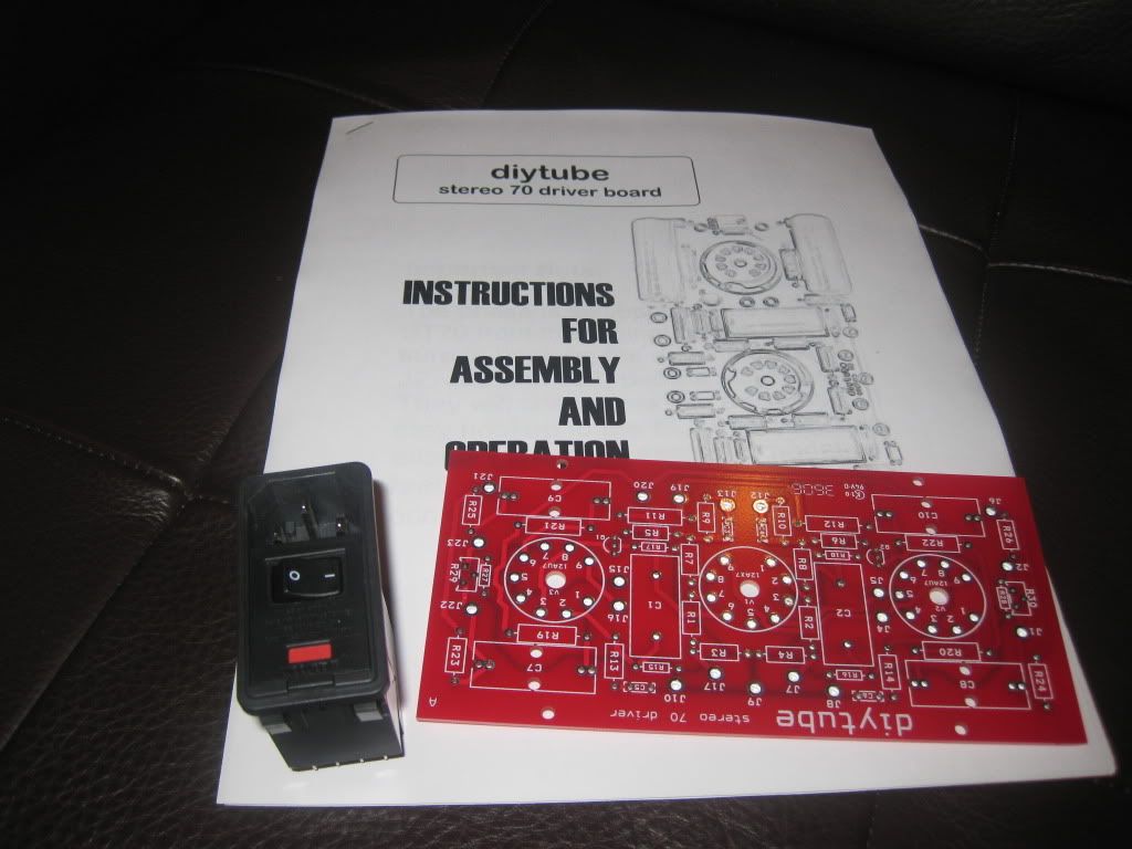
Start getting some parts.
Thanks to Shannon for beautiful board!
Image
MrMiele
 
Posts: 26
Joined: Tue Feb 08, 2011 5:59 pm
Location: Los Angeles, CA

Postby MrMiele » Tue Feb 22, 2011 7:50 pm

Today I have received lots of parts and chassis. Actual working space is 11.1/4 x 9.5 Very limited space! But this chassis is gorgeous!
Here where I'm now.
Image

I wondering if some one have dimensions of opening I have to cut for transformer PA060.
MrMiele
 
Posts: 26
Joined: Tue Feb 08, 2011 5:59 pm
Location: Los Angeles, CA

Postby TomMcNally » Tue Feb 22, 2011 8:55 pm

I'd wait to have the transformer in hand before cutting any holes.
Using the actual parts as templates is always the best way.
User avatar
TomMcNally
Darling du Jour
 
Posts: 2729
Joined: Sat Nov 19, 2005 2:19 pm
Location: Northfield, NJ

Postby MrMiele » Tue Feb 22, 2011 9:14 pm

Right. I have no choice.. Will wait for couple of days. O:)
MrMiele
 
Posts: 26
Joined: Tue Feb 08, 2011 5:59 pm
Location: Los Angeles, CA

Postby Writer Frog » Wed Feb 23, 2011 9:39 pm

MrMiele wrote:I wondering if some one have dimensions of opening I have to cut for transformer PA060.

Dynakitparts has a drawing for the PA-060:

http://www.dynakitparts.com/store/schematics/PA-060.pdf

Image
/Matt
User avatar
Writer Frog
 
Posts: 95
Joined: Mon Mar 06, 2006 9:17 am

Postby MrMiele » Thu Feb 24, 2011 10:09 am

Thanks a lot!
MrMiele
 
Posts: 26
Joined: Tue Feb 08, 2011 5:59 pm
Location: Los Angeles, CA

A few hints and suggestions

Postby EWBrown » Thu Feb 24, 2011 3:19 pm

Before you "commit" the back panel locations for the IEC AC power input, the two sets of speaker binding posts, and the two PSU caps, you should first determine the exact power and output transformer mounting locations.

It so easier, and less problems, to have all the transformer mounting and wiring access holes already in place, before mounting the rear panel components. This is a situation in which the infamous "Colonel Murphy" can, and will, do his worst - if anything can go wrong, it will.

As the old saying goes, measure three times, then cut (or drill, punch, etc).

I just did some quick measurements on my "original" ST70, and the trannies should fit, though the spacing between them will be fairly tight.


If you should run into a situation in which all three transformers will not fit across the chassis, as it is almost two inches narrower than the original ST70, then the power transformer PA-060 could be mounted upright (like the two output transformers), though this will require obtaining two properly-sized endbells.


These may be available through Triode Electronics, or "The Tube Zone". I can check through my stuff, I may have some unused, appropriate endbells, if you should require them.

In this situation the orientation of the two OPT, s and the power transformer cores will have to be at 90 degrees relative, in order to prevent any magnetically-induced AC field coupling from the power trannie to the two outputs.


Before you start any serious drilling, punching and cutting of the chassis top, get some of the blue painter's masking tape, and cover the top completely, this will help to prevent any accidental scratches, and the tape can be easily marked for the hole locations. The blue tape's sticky side is designed not to leave residue behind once it is removed.

HTH

/ed B in NC
Real Radios Glow in the Dark
User avatar
EWBrown
Insulator & Iron Magnate
 
Posts: 6389
Joined: Wed Mar 19, 2003 6:03 am
Location: Now located in Clay County, NC !

Postby TomMcNally » Thu Feb 24, 2011 4:07 pm

Like Steve at Angela Instruments http://angela.com states, and I've often repeated:

The best advice I can give you is to NEVER drill any holes
in a chassis until you actually have all of the parts on hand.
User avatar
TomMcNally
Darling du Jour
 
Posts: 2729
Joined: Sat Nov 19, 2005 2:19 pm
Location: Northfield, NJ

Postby Geek » Thu Feb 24, 2011 6:14 pm

TomMcNally wrote:Like Steve at Angela Instruments http://angela.com states, and I've often repeated:

The best advice I can give you is to NEVER drill any holes
in a chassis until you actually have all of the parts on hand.


AMEN!!!!!!!
-= Gregg =-
Fine wine comes in glass bottles, not plastic sacks. Therefore the finer electrons are also found in glass bottles.
User avatar
Geek
KT88
 
Posts: 3585
Joined: Sun Oct 21, 2007 3:01 am
Location: Chilliwack, British Columbia

Re: A few hints and suggestions

Postby Brik » Thu Feb 24, 2011 10:01 pm

After ordering the parts for a new build, I usually have 4 weeks to plan for the chassis layout. The stingy one that I am, I use the free FrontPanel Designer software and get a general idea of that the build would look like.
We can usually get mechanical drawings for the parts from the net, or we can measure the ones in stock, we can define macro shapes representing major parts out of the engraving and hole objects.

Here is an FPD drawing of an ECL86/6GV8/6F5P SET under construction:
Image

This way, it is possible to get a general idea of what the layout could be without having a single part on hand.
And the drawings can be printed out on a whole-sheet label paper to be used as drilling templates:
Image
/b
User avatar
Brik
 
Posts: 204
Joined: Fri Apr 07, 2006 5:30 pm
Location: West of Boston

Postby MrMiele » Thu Feb 24, 2011 11:59 pm

Thank you guys for your help and advices!
I'm not touching chassis till all parts will be delivered. I have all parts in, accept transformers (ordered kit from triodeelectronics).
I'm planing to use unibits to drill holes for tube sockets. Any recommendations?
MrMiele
 
Posts: 26
Joined: Tue Feb 08, 2011 5:59 pm
Location: Los Angeles, CA

Postby MrMiele » Fri Feb 25, 2011 12:07 am

Here is better picture. Hope all transformers will fit....

Image
MrMiele
 
Posts: 26
Joined: Tue Feb 08, 2011 5:59 pm
Location: Los Angeles, CA

Postby Ty_Bower » Fri Feb 25, 2011 7:09 am

MrMiele wrote:I'm planing to use unibits to drill holes for tube sockets. Any recommendations?

Practice on a scrap piece of metal if you've never done this before.

Drill a small (1/16") pilot hole first, with a regular bit. Do this for every hole on the chassis (tube holes, wiring holes under transformers, bolt holes, etc). I like to use a printed-to-scale template, which I tape to the top of the metal. Then I drill a pilot hole through the template at every point. Peel off the template and finish enlarging all the holes. Keep in mind that swarf will creep under the paper and scratch the chassis. If this is a problem, wrap the chassis in blue painters tape as previously described.

Image

Use progressively larger bits to enlarge the holes. Do this even for the hole you will eventually drill with the unibit. After they have been enlarged once or twice, then they are ready for the unitbit.

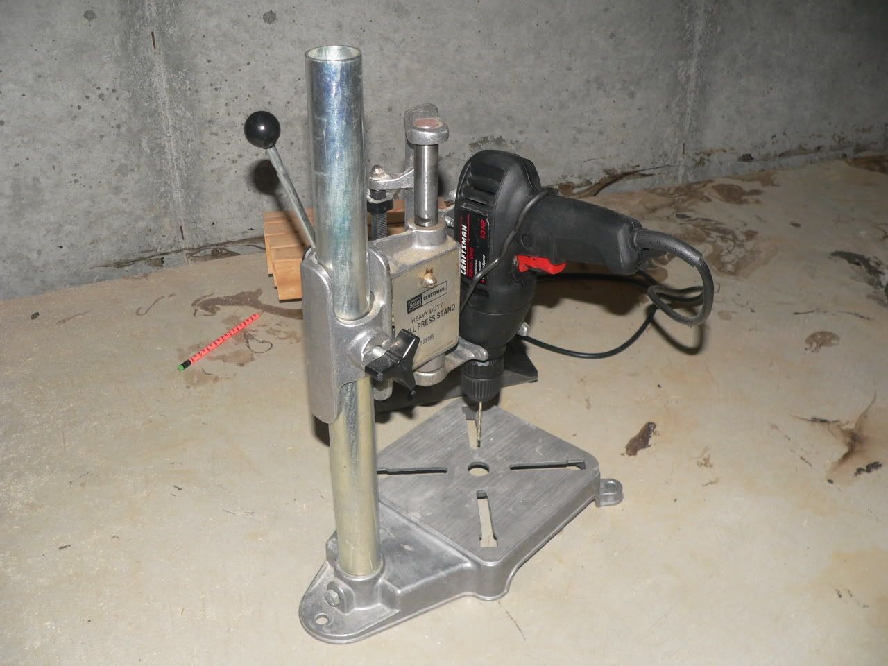
Use a small press stand, or better yet a drill press for the unibit. In fact, use it for all the drilling. Keep an eye on the unibit as you drill. While it generally tends to drill "straight", it can be encouraged to wander if you apply a slight sideways force to the piece. This can make a hole end up in slightly the wrong spot. The unibit will also wander if it hits a soft spot in the chassis, like an old hole that was patched with JB weld.

Image
"It's a different experience; the noise occlusion, crisp, clear sound, and defined powerful bass. Strong bass does not corrupt the higher frequencies, giving a very different overall feel of the sound, one that is, in my opinion, quite unique."
User avatar
Ty_Bower
KT88
 
Posts: 1494
Joined: Wed Mar 21, 2007 2:50 pm
Location: Newark, DE

Postby TomMcNally » Fri Feb 25, 2011 9:15 am

I learned something!

swarf (swɔːf, swɑːf)

— n
1. material removed by cutting or grinding tools in the machining of metals, stone, etc
2. radioactive metal waste from a nuclear power station
3. small fragments of disintegrating spacecraft, orbiting the earth

[C16: of Scandinavian origin; related to Old Norse svarf metallic dust]
User avatar
TomMcNally
Darling du Jour
 
Posts: 2729
Joined: Sat Nov 19, 2005 2:19 pm
Location: Northfield, NJ

Postby MrMiele » Tue Mar 01, 2011 10:52 am

Received transformes and choke today. What is the difference PA060S power transformer vs PA060 ?
MrMiele
 
Posts: 26
Joined: Tue Feb 08, 2011 5:59 pm
Location: Los Angeles, CA

PreviousNext

Return to st70

Who is online

Users browsing this forum: Google [Bot] and 11 guests