by EWBrown » Thu Feb 24, 2011 3:19 pm
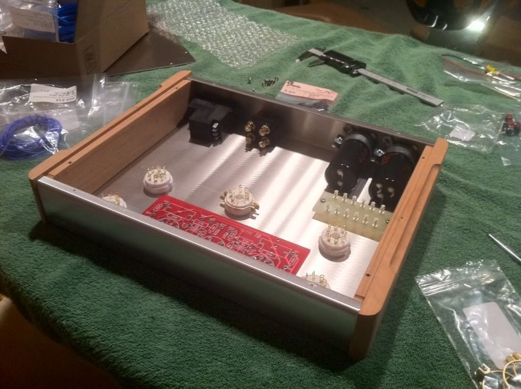
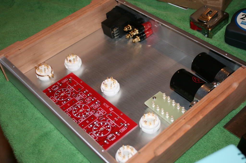
Before you "commit" the back panel locations for the IEC AC power input, the two sets of speaker binding posts, and the two PSU caps, you should first determine the exact power and output transformer mounting locations.
It so easier, and less problems, to have all the transformer mounting and wiring access holes already in place, before mounting the rear panel components. This is a situation in which the infamous "Colonel Murphy" can, and will, do his worst - if anything can go wrong, it will.
As the old saying goes, measure three times, then cut (or drill, punch, etc).
I just did some quick measurements on my "original" ST70, and the trannies should fit, though the spacing between them will be fairly tight.
If you should run into a situation in which all three transformers will not fit across the chassis, as it is almost two inches narrower than the original ST70, then the power transformer PA-060 could be mounted upright (like the two output transformers), though this will require obtaining two properly-sized endbells.
These may be available through Triode Electronics, or "The Tube Zone". I can check through my stuff, I may have some unused, appropriate endbells, if you should require them.
In this situation the orientation of the two OPT, s and the power transformer cores will have to be at 90 degrees relative, in order to prevent any magnetically-induced AC field coupling from the power trannie to the two outputs.
Before you start any serious drilling, punching and cutting of the chassis top, get some of the blue painter's masking tape, and cover the top completely, this will help to prevent any accidental scratches, and the tape can be easily marked for the hole locations. The blue tape's sticky side is designed not to leave residue behind once it is removed.
HTH
/ed B in NC
Real Radios Glow in the Dark