Stock board diagram has eyelet #9 (GND) marked with a ''D''

Posted:
Fri Apr 23, 2010 3:21 pmby 20to20
Is this a common knowledge thing here? Do I have an outdated bootleg manual? I assume it should be GN''D'' printed there. Not a 435v. TP.
Posted:
Fri May 21, 2010 8:34 amby Bob01605
20to20,
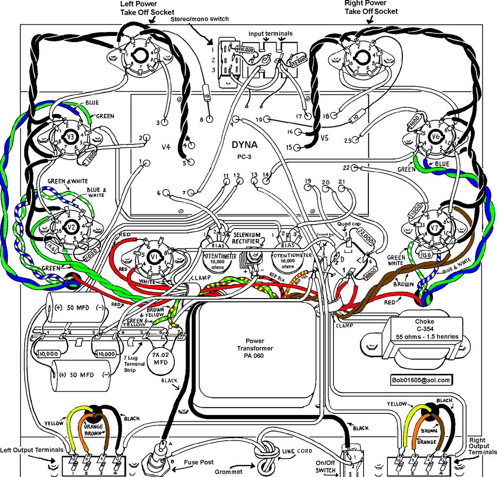
You must have an altered manual or altered pictorial. Below is an ST-70 pictorial that I scanned myself from an original Dynaco ST-70 pictorial. I colored in the transformer wires but the eyelet markings on the driver board are exactly the same. Eyelet # 9 is a ground eyelet for the board and grounds the driver board to the "star ground" next to the quad cap. There is no "G" or "GND" marking on the original driver board or the original pictorial. It is just marked as eyelet "9" on the driver board and on the pictorial.
Bob Latino
Posted:
Fri May 21, 2010 9:45 amby 20to20
Hey Bob,
It's on the schematic in the Dynaco manual. If someone were troubleshooting they might mistake the diagram marking of the eyelet for a 435v. test point and find nothing until they looked farther. I think the original was to have been marked "GND", if anything.
That's really a great drawing you did, BTW. I'm sure it will endure through history as a superior reference doc, to guide future builders long after the colors of the original leads have faded.
Posted:
Fri May 21, 2010 11:22 amby Ty_Bower
Are we talking about the point circled in the schematic below?
Posted:
Fri May 21, 2010 12:42 pmby 20to20
Ty_Bower wrote:Are we talking about the point circled in the schematic below?
No. It's the board diagram
Posted:
Sat May 22, 2010 9:27 amby Ty_Bower
Dunno. It seems clear that eyelet should be tied to ground. I couldn't tell you why it has a D printed near it. Page six of the assembly manual says:
65 ( ) Connect one end of a 5" wire to eyelet #9
(S). Connect the other end to solder lug
near filter capacitor.
