Hi all,
I was hoping to get some assistance if anyone has some ideas. I am totally stuck trying to figure out what I did wrong or what might be bad on my new Triode ST-70 kit.
I have checked and rechecked every connection. Today I spent 4 hours checking all the resistors on the STS cap board (I removed the board completely from the amp and then desoldered and tested all resistors) and then looking over the circuit again for any possible shorts or other problems. I did find a spot on the choke wire where the sheath had been damaged, I put some heatshrink tubing over it. I thought maybe that was the problem, so I put another fuse in and within 20 seconds the fuse blew. Before I was able to run the amp for a while and the fuse would only blow if I attempted to bias the amp past .9V. Also, when I did a sound check I only got sound from the right channel, and I did swap output tubes and preamp tubes trying to troubleshoot but there was no change, that was before the work I did today.
I checked the resistance of the choke, it is 52ohms. I have also tested both output transformers, and they check out fine, at least by testing resistances according to a guide by Bob Latino.
At this point I think the problem is in the STS cap board, but I dont know for sure, maybe one of the caps is bad? I dont have a capacitance tester, but I could get one if needed.
I am sure there is other info that would be helpful in providing suggestions, but I dont know what is helpful at this point, my knowledge of troubleshooting tube amps is limited. If there is something to check, let me know...I would really appreciate help anyone can provide. I am getting frustrated to no end, I built the amp over a month ago, then didnt get to do much troubleshooting until the last week or two... I did contact Triode via email several days ago and have not heard back, unfortunately their store hours are while I am at work so calling them is not a realistic option unless I skip lunch. I am starting to wish I had not bought this amp, I know thats extreme but the frustration is getting the best of me.
Thanks all,
Greg
495V on pin3/4 of output tubes, new Triode ST-70 build
50 posts
• Page 1 of 4 • 1, 2, 3, 4
495V on pin3/4 of output tubes, new Triode ST-70 build
![]() by gregk » Sat Mar 13, 2010 3:58 pm
by gregk » Sat Mar 13, 2010 3:58 pm
- gregk
- Posts: 25
- Joined: Mon Mar 08, 2010 9:06 am
![]() by Ty_Bower » Sat Mar 13, 2010 4:39 pm
by Ty_Bower » Sat Mar 13, 2010 4:39 pm
You've used some extreme troubleshooting methods. I'm not sure I'd recommend desoldering all the resistors from the board just to check their values. You run the risk of causing new problems when you put them back in.
Blowing fuses is nearly always caused by a short circuit somewhere. The best way to find shorts is with the amp powered off and unplugged. Get a copy of the schematic in front of you. Check the power supply caps with your voltmeter to confirm they are discharged. Test each point along the B+ rail, starting from the rectifier and working your way to the anodes of the power tubes. You want to see a nice high resistance between the test point and ground. A meg ohm is great, 100K might be OK, but 10K is suspect. Check the schematic and see if there are any bleeder resistors between B+ and ground. Keep in mind the caps in the power supply will appear as a low resistance at first, then slowly increase in resistance.
Possible causes of a short might be a wiring error, a faulty power supply cap, or a bad rectifier or power tube. You could also have a short somewhere on one of the heater circuits. Try powering up the amp with all the tubes except for the rectifier tube. If it doesn't blow the fuse, the heater wiring is probably OK.
If you have a digital camera, take some high resolution photos of your wiring. Upload your pictures to your favorite hosting site (I like Photobucket.com), and post the links here so we can take a look.
Welcome to DIYtube. :)
"It's a different experience; the noise occlusion, crisp, clear sound, and defined powerful bass. Strong bass does not corrupt the higher frequencies, giving a very different overall feel of the sound, one that is, in my opinion, quite unique."
-

Ty_Bower - KT88
- Posts: 1494
- Joined: Wed Mar 21, 2007 2:50 pm
- Location: Newark, DE
Re: 495V on pin3/4 of output tubes, new Triode ST-70 build
![]() by Writer Frog » Sat Mar 13, 2010 7:06 pm
by Writer Frog » Sat Mar 13, 2010 7:06 pm
Hi Greg,
I second Ty's welcome to DYITube.
As I understand from your post, you have the following two symptoms:
1. The fuse blows in 20 seconds of power on.
2. There is no sound from the left channel.
A bad cap (or, for that matter, any component) in the cap board cannot cause just the left channel to fail. So the left channel problem is not caused by the cap board.
After doing what Ty suggested, I would do the following:
a) Check the fuse. It should be the 3.0A slow blow type.
b) Check the continuity of the Ground connection from the center tap of the secondary HT
to the ground trace of the driver board. It should be close to 0 ohms.
c) Power up the amp with all the tubes pulled out. See if the fuse blows.
If the fuse blows, you might have a bad power transformer.
Check the AC voltage levels of HT secondary. It should be 350V AC (+- 10%).
Check the DC voltage levels at each pin 5 (Grid) of all the power tubes.
The voltage should be -35V ~ -45V. Adjust the bias pots so that you see the "most negative" voltage (-45V, perhaps?) at each pin. If you cannot adjust the bias voltage more negative than -35V, you have a problem with the bias circuit.
c) Power up the amp with just the rectifier tube plugged in.
If the fuse blows, there may be a problem with how the rectifier tube is wired.
Check the DC voltage level at pin 8 (filament/cathode) of the rectifier tube.
The voltage could be anywhere from 450V to 520V.
Switch off the amp as soon as you make voltage measurements.
d) Power up the amplifier with all the tubes plugged in. Check the voltage levels against the schematic. If there is any discrepancy of more than 20%, you can narrow down the problem area from there.
/Matt
-

Writer Frog - Posts: 95
- Joined: Mon Mar 06, 2006 9:17 am
![]() by gregk » Sat Mar 13, 2010 9:58 pm
by gregk » Sat Mar 13, 2010 9:58 pm
Ty - thanks for the reply, you are right that my troubleshooting is not recommended, I just didnt know what else to do at the time. I've tested more things than I can even recall at this point. I am working without a Triode version of the schematic, I just have an original Dynaco ST-70 schematic and Triodes build instructions which only tells you what to solder where. I am waiting on Triodes response, which will hopefully include a schematic which I have asked for.
Writer Frog - thanks for the reply. It was my understanding from Triode's ST-70 troubleshooting page (which I think it not specific to their kit, just ST-70's in general) specified that the voltage should be from 375V-475V at the output transformer pins of the output tubes. I've had another person tell me it should be 450V, and the original Dynaco schematic says 410-415V...so I am not sure what is correct. Also, Triode specifies a 2.5A slow blow fuse, which is what I have been using.
I will go through the troubleshooting steps that both of you provided as soon as possible (hopefully tomorrow), in the meantime I did get some pics of what it looks like now. It looks bad after moving stuff around and trying to figure it out, it was nice and pretty for the most part when I first built it. The pics posted here are only 1024x683, if you want the full res from my cam, check my Flickr photostream linked below, open the pic and go to All Sizes. Here is a link to my ST-70 pics on Flickr:
http://www.flickr.com/photos/gkemp/sets/72157623395684980/
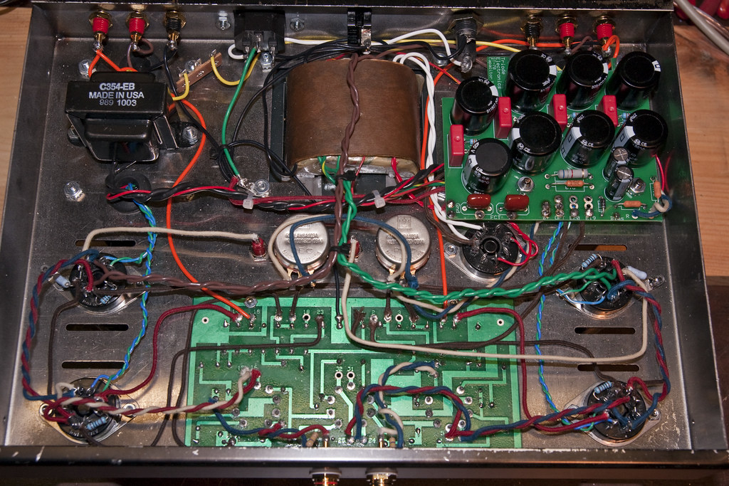
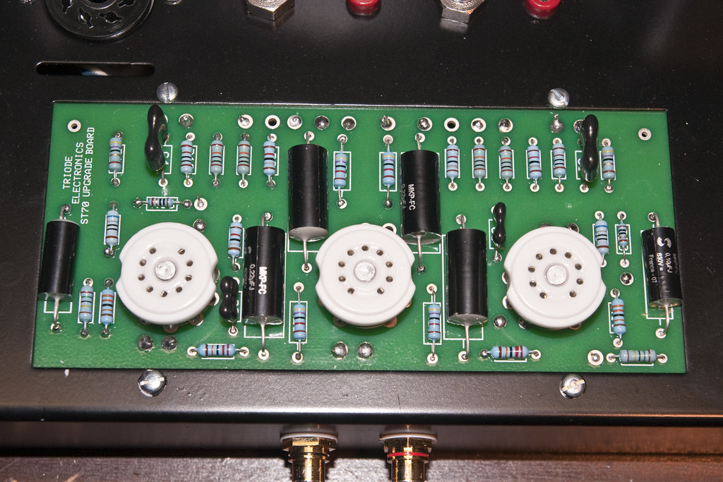
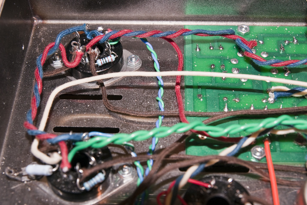
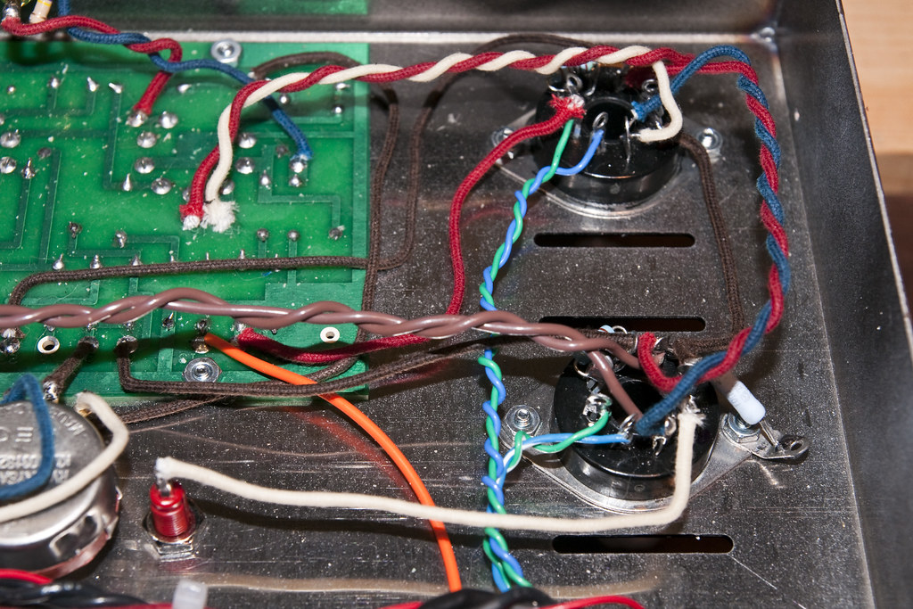
I will let you know what I find out from the recommended troubleshooting.
Thanks!
Greg
Writer Frog - thanks for the reply. It was my understanding from Triode's ST-70 troubleshooting page (which I think it not specific to their kit, just ST-70's in general) specified that the voltage should be from 375V-475V at the output transformer pins of the output tubes. I've had another person tell me it should be 450V, and the original Dynaco schematic says 410-415V...so I am not sure what is correct. Also, Triode specifies a 2.5A slow blow fuse, which is what I have been using.
I will go through the troubleshooting steps that both of you provided as soon as possible (hopefully tomorrow), in the meantime I did get some pics of what it looks like now. It looks bad after moving stuff around and trying to figure it out, it was nice and pretty for the most part when I first built it. The pics posted here are only 1024x683, if you want the full res from my cam, check my Flickr photostream linked below, open the pic and go to All Sizes. Here is a link to my ST-70 pics on Flickr:
http://www.flickr.com/photos/gkemp/sets/72157623395684980/
I will let you know what I find out from the recommended troubleshooting.
Thanks!
Greg
- gregk
- Posts: 25
- Joined: Mon Mar 08, 2010 9:06 am
![]() by Writer Frog » Sun Mar 14, 2010 7:57 pm
by Writer Frog » Sun Mar 14, 2010 7:57 pm
gregk wrote:...It was my understanding from Triode's ST-70 troubleshooting page (which I think it not specific to their kit, just ST-70's in general) specified that the voltage should be from 375V-475V at the output transformer pins of the output tubes. I've had another person tell me it should be 450V, and the original Dynaco schematic says 410-415V...so I am not sure what is correct.
The DC voltage level you would have at the anode tap of the output transformer depends greatly on the following:
1. If the power supply has a cLC filter, the change of the first capacitor value from 5uF to 50uF can increase the output voltage by 50V depending on the inductance of the choke.
2. Unloaded power supply B+ voltage can be significantly higher than the properly loaded one. With just the rectifier tube inserted, the power supply is unloaded, and the voltage reading will be significantly higher than the normal operating voltage.
3. The voltage variation at the wall outlet has a non-trival impact on the B+ voltage. Have measured your household AC voltage?
Also, Triode specifies a 2.5A slow blow fuse, which is what I have been using.
The original Dynaco Stereo 70 schematic specifies a 3.0A fast blow fuse.

The amp dissipates ~200W in a quiescent state. so a 3.0A one is more appropriate.
The ST-70 manual recommends the slow blow type if the fuse blows frequently.
/Matt
-
Writer Frog - Posts: 95
- Joined: Mon Mar 06, 2006 9:17 am
![]() by antiquekid3 » Sun Mar 14, 2010 8:34 pm
by antiquekid3 » Sun Mar 14, 2010 8:34 pm
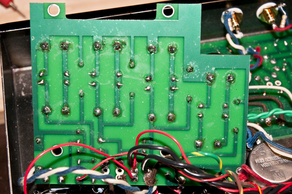
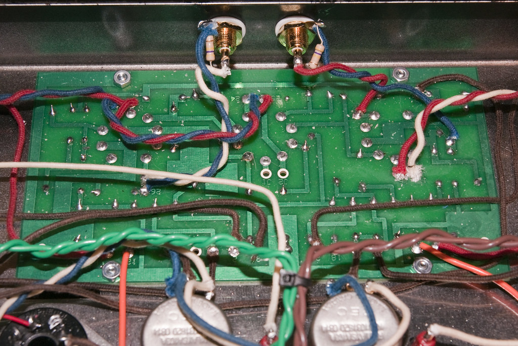
You did a really nice job putting it together, but I do see some solder joints that look as though they need more flux and heating of the traces instead of the component leads. Those that have a round, bulbous look should probably be corrected so they look more like a cone, if you know what I mean.
Don't get me wrong; I have seen MUCH worse soldering skills!! :-)
http://img715.imageshack.us/img715/8600/img0191m.jpg
http://img715.imageshack.us/img715/2774/img0189g.jpg
That piece of crap came out of a piece of electronics someone had (unsuccessfully) tried to make. I think he ended up using a whole 1lb spool of Ersin solder! :-P
Kyle
-

antiquekid3 - Posts: 166
- Joined: Thu Feb 04, 2010 9:14 pm
![]() by gregk » Tue Mar 16, 2010 5:36 pm
by gregk » Tue Mar 16, 2010 5:36 pm
Well, it was tiny little jumper wire that I was missing. I got a response from Triode (which was actually very fast once I realized that the email address on their website was wrong and that Gmail put the Failure Notice in my Spam folder and I sent a new message). They suggested I was missing the required jumper wire that is needed for the 12au7 tube. I added the wire as they suggested and now both channels run fine and I get sound from both. I still cannot bias that amp all the way up - this is probably fuse related (at least I hope) - as Writer Frog has said - but I want to hear it from Triode before I try a 3A fuse. Basically anything voids their warranty, and I would prefer not to void the warranty before it runs out.
I thought maybe I missed the jumper wire requirement in their build instructions, nope it is not mentioned at all, then after more closely examining the pics in their build guide and noticed that the eyelets for the jumper do not exist on the version of the board in the instructions. I let them know that they should get the documentation updated, or at least tell people they also need to review the separate EF86 driver board and STS cap board instructions as well as the main guide. I was very careful about going over the main build instructions meticulously, but I only used the other guides for reference.
This is my second tube kit build, and I have a single ended tube guide amp that I mostly built from scratch but never finished wiring, its a design from AX84. I need to finish it. My other tube amp kit was the S5 K-12G which is still going strong after 5 years. I didnt get to learn anything with that amp, it took 2 hours to build and everything worked perfectly! The ST-70 was a learning experience...
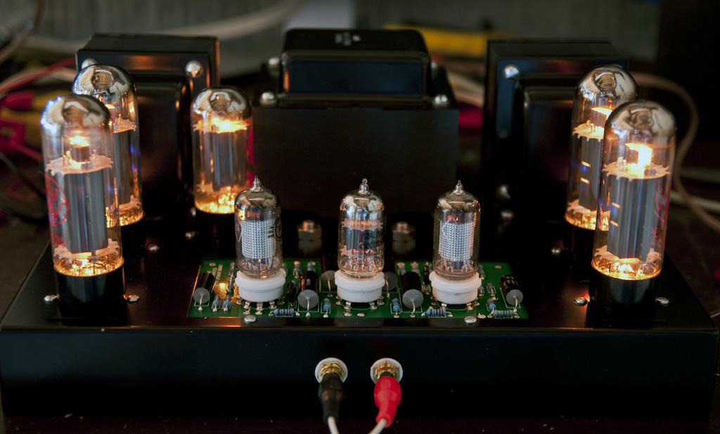
Anyhow, here is a pic of the ST-70 now that it is mostly working (this is a 15 second exposure, the tubes do not run that bright!)
Thanks for all the suggestions provided!
Greg
I thought maybe I missed the jumper wire requirement in their build instructions, nope it is not mentioned at all, then after more closely examining the pics in their build guide and noticed that the eyelets for the jumper do not exist on the version of the board in the instructions. I let them know that they should get the documentation updated, or at least tell people they also need to review the separate EF86 driver board and STS cap board instructions as well as the main guide. I was very careful about going over the main build instructions meticulously, but I only used the other guides for reference.
This is my second tube kit build, and I have a single ended tube guide amp that I mostly built from scratch but never finished wiring, its a design from AX84. I need to finish it. My other tube amp kit was the S5 K-12G which is still going strong after 5 years. I didnt get to learn anything with that amp, it took 2 hours to build and everything worked perfectly! The ST-70 was a learning experience...
Anyhow, here is a pic of the ST-70 now that it is mostly working (this is a 15 second exposure, the tubes do not run that bright!)
Thanks for all the suggestions provided!
Greg
- gregk
- Posts: 25
- Joined: Mon Mar 08, 2010 9:06 am
![]() by gregk » Tue Mar 16, 2010 5:39 pm
by gregk » Tue Mar 16, 2010 5:39 pm
Oh, and to antiquekid - thanks for the tips on the soldering. I did go over most of the joints to make them more correct. I did take a class on soldering about 6 years ago, but I wasn't the best at it and I dont get much practice...
- gregk
- Posts: 25
- Joined: Mon Mar 08, 2010 9:06 am
![]() by Writer Frog » Wed Mar 17, 2010 12:03 pm
by Writer Frog » Wed Mar 17, 2010 12:03 pm
Hi Greg,
Congratulations on your new ST-70. Well done!
I hope you have a great time listening to your new masterpiece.
Regarding the jumper setting.
I suspect the issue is the different heater connection between a 12.6V tube like a 12AU7 and a 6.3V tube like a 6CG7. For a 12AU7, the pins 4 and 5 must be tied together and the 6.3V heater voltage connection is made between the pins 4/5 (tied) and pin 9. It is possible that you only had power to one side of the dual triode heater (between pins 4 and 9, but not between pins 5 and 9) resulting in no sound from one channel.

Regarding soldering technique, you'll be better off using a soldering iron with at least 40W, and preferably something more powerful. Most of the tube amplifier components are pretty tolerant of heat with the notable exception of silicon diodes and occasional constant current sink ICs. More powerful soldering iron lets you make a solid connection quicker.
Have fun!
Congratulations on your new ST-70. Well done!
I hope you have a great time listening to your new masterpiece.
Regarding the jumper setting.
I suspect the issue is the different heater connection between a 12.6V tube like a 12AU7 and a 6.3V tube like a 6CG7. For a 12AU7, the pins 4 and 5 must be tied together and the 6.3V heater voltage connection is made between the pins 4/5 (tied) and pin 9. It is possible that you only had power to one side of the dual triode heater (between pins 4 and 9, but not between pins 5 and 9) resulting in no sound from one channel.
Regarding soldering technique, you'll be better off using a soldering iron with at least 40W, and preferably something more powerful. Most of the tube amplifier components are pretty tolerant of heat with the notable exception of silicon diodes and occasional constant current sink ICs. More powerful soldering iron lets you make a solid connection quicker.
Have fun!
/Matt
-
Writer Frog - Posts: 95
- Joined: Mon Mar 06, 2006 9:17 am
![]() by Ty_Bower » Wed Mar 17, 2010 2:28 pm
by Ty_Bower » Wed Mar 17, 2010 2:28 pm
Writer Frog wrote:Regarding soldering technique, you'll be better off using a soldering iron with at least 40W, and preferably something more powerful.
Too much power without any kind of temperature control is just going to scorch boards and lift traces. The best ~$45 I spent (on a soldering iron) was this Aoyue 936. It makes soldering so much more reliable.

"It's a different experience; the noise occlusion, crisp, clear sound, and defined powerful bass. Strong bass does not corrupt the higher frequencies, giving a very different overall feel of the sound, one that is, in my opinion, quite unique."
-
Ty_Bower - KT88
- Posts: 1494
- Joined: Wed Mar 21, 2007 2:50 pm
- Location: Newark, DE
![]() by Ty_Bower » Wed Mar 17, 2010 7:24 pm
by Ty_Bower » Wed Mar 17, 2010 7:24 pm
I think I bought mine off eBay. I've also noticed they're sold at Stan Rubinstein Associates for a reasonable price.
It's a knockoff of a very similar Hakko model. The Hakko is much higher wattage (the Aoyue is "only" 35 watt). Still, the Aoyue works perfectly for what I need, even soldering octal sockets. I'm betting it won't work very well for soldering ground connections to the chassis (I haven't tried). The big plus is that the Hakko will cost you double what you would pay for the Aoyue. It was an easy choice for me.
It's a knockoff of a very similar Hakko model. The Hakko is much higher wattage (the Aoyue is "only" 35 watt). Still, the Aoyue works perfectly for what I need, even soldering octal sockets. I'm betting it won't work very well for soldering ground connections to the chassis (I haven't tried). The big plus is that the Hakko will cost you double what you would pay for the Aoyue. It was an easy choice for me.
"It's a different experience; the noise occlusion, crisp, clear sound, and defined powerful bass. Strong bass does not corrupt the higher frequencies, giving a very different overall feel of the sound, one that is, in my opinion, quite unique."
-
Ty_Bower - KT88
- Posts: 1494
- Joined: Wed Mar 21, 2007 2:50 pm
- Location: Newark, DE
![]() by SDS-PAGE » Wed Mar 17, 2010 7:55 pm
by SDS-PAGE » Wed Mar 17, 2010 7:55 pm
Or just get one of these of 12 bones: http://www.parts-express.com/pe/showdetl.cfm?Partnumber=374-100
I primarily solder point-to-point and it works great on soldering connections to the chassis.
I primarily solder point-to-point and it works great on soldering connections to the chassis.
-

SDS-PAGE - KT88
- Posts: 865
- Joined: Thu Feb 22, 2007 4:41 pm
- Location: Brandon, SD
![]() by Ty_Bower » Wed Mar 17, 2010 8:04 pm
by Ty_Bower » Wed Mar 17, 2010 8:04 pm
There's no temperature sensing element in that kind. Sure, you can dial the wattage up or down, but the heater doesn't kick in when the tip gets cold. It doesn't back down the power when it gets too hot, either. If you've got a variac, you could just plug in your $3, 40 watt Radio Shack iron and have the same thing.
"It's a different experience; the noise occlusion, crisp, clear sound, and defined powerful bass. Strong bass does not corrupt the higher frequencies, giving a very different overall feel of the sound, one that is, in my opinion, quite unique."
-
Ty_Bower - KT88
- Posts: 1494
- Joined: Wed Mar 21, 2007 2:50 pm
- Location: Newark, DE
P
![]() by Writer Frog » Wed Mar 17, 2010 8:35 pm
by Writer Frog » Wed Mar 17, 2010 8:35 pm
Hi,
Larger Wattage iron does not necessarily have a higher tip temperature. Rather, it does have a larger thermal mass - it can heat the given object to the soldering temperature quicker, not necessarily hotter.
I primarily do point-to-point also, and my pretty good 30W Weller cannot cut it in anything beyond soldering resistors and caps to PCBs.
For point-to-point connections involving a premium octal socket with massive lugs, I usually need at least a 40 Watter. As for the "star ground lug complex" that is bolted to the chassis, I usually need a 60 Watter or larger iron. The larger iron is much better at heating the target metals to soldering temperatures much quicker before the heat is conducted away and get the connections done quickly and cleanly. If you use a smaller iron, you have to keep the iron on the target metals much longer which results in heat conduction "collateral damage" to surrounding areas that may have plastic items, wire insulators, etc.
Of course, your milage may vary....
/Matt
-
Writer Frog - Posts: 95
- Joined: Mon Mar 06, 2006 9:17 am
50 posts
• Page 1 of 4 • 1, 2, 3, 4
Who is online
Users browsing this forum: No registered users and 9 guests