Page 1 of 3
Making an ST-70 Driver Board

Posted:
Thu Feb 04, 2010 9:45 pmby antiquekid3
I'm new here. I have an ST-70 in pretty rough shape that I plan on fully restoring. I've already started taking pictures from the get-go, so I should have some great before and after pictures!
This is an older model with the A470 output transformers. They appear to be in good shape.
Someone's already recapped the thing and removed the choke. Luckily I found a decent replacement. (1.2H, 60ΩDC)
However, the thing is, I am a cheap high school student. I refuse to spend a lot on this restoration, but I really want a new chassis. So if I get a new chassis, I won't want to spend a lot on the rest of it.
I have successfully made some PC boards before, so I am up for the challenge of making a driver board. Firstly, it has to be single-sided. Secondly, I would like to avoid the 7199s, so a 12AX7/12AU7 board or something close would be great. I also want extensive documentation for how to hook it up to the rest of the amp. Schematics, etc.
I don't have any CAD software, so if someone has a B&W picture of the layout, that'd be awesome!
Anyone have any suggestions?
Kyle
Posted:
Thu Feb 04, 2010 10:26 pmby Geek
Hi, welcome!
You can begin by checking around here for what others did for ideas and inspiration. Some of us documented our restorations.
I hated the ST-70 look and changed it significantly:
http://geek.scorpiorising.ca/dynamutt.html
Cheers!
Posted:
Thu Feb 04, 2010 10:38 pmby antiquekid3
Thanks!
Wow, that looks great! Though your ST-70 doesn't look at all original, it'd look great next to a Garrard 301 with a similarly-styled plinth! :-)
I am all for the original Dynaco look, but not necessarily the original driver board.
To be honest, I really don't know what I want. I do want it to sound good (DUH!), but I really don't know if I want triode/UL/pentode operation or not. I don't know if I want 4 bias controls or just two.
I do know that from the outside, I want it to look pretty much the same.
And are (2) 200µF 200V caps okay for the bias in the original circuit? I found a pretty can (NOS) that I would like to stick in place of the missing can. I figure I can use the values for the bias. I'll have (4) 30µF to 50µF 525V caps for the power supply.
Kyle
Posted:
Fri Feb 05, 2010 6:36 amby Quad
Posted:
Fri Feb 05, 2010 10:19 amby snitch56
Terry Smith did a point-to-point driver for his ST-70. Could be an option if you can get a hold of the schematic.
http://www.diytube.com/phpBB2/viewtopic.php?t=2991
Posted:
Fri Feb 05, 2010 3:03 pmby antiquekid3
I looked at the KTA board. The problem I have is the new boards are two-sided with nice labels, and the rough photocopy of the old board has a bunch of traces that appear to go to nowhere and isn't labeled. If the older board were better documented, I'd definitely build it.
If I can find a 6SN7 circuit to use (and understand...), I might try laying out my own board. This Blackburn board looks cool, but can someone explain to me what he's doing with the output transformer? I can build tube stuff all day, but I'm not to the point of understanding all of the different classes of amps and feedback circuitry.
http://www.blackburnaudio.com/schematic ... 7-st70.bmp
Kyle
Posted:
Fri Feb 05, 2010 3:34 pmby mesherm
This Blackburn board looks cool, but can someone explain to me what he's doing with the output transformer?
If you mean the connection from the speaker output lead to the base of the first stage thats just a negative feedback loop. Its pretty much a stock ST70 circuit except with an SRPP (shunt regulated push pull) voltage amp stage instead of a pentode grounded cathode.
The half section of 6SN7 with the 22k resistors top and bottom is a cathodyne phase splitter which provides equal but opposite signals to the push pull output tubes. The 22k resistors should be very closely matched (1% or better). Its a good circuit but provides a gain of less than 1 so all the amplification has to come from the first stage. In the original ST70 that was a pentode grounded cathode circuit. The reason they didn't do something like this was it takes 3 tubes instead of 2...remember that cost was a major factor.
The Blackburn driver circuit should perform great with the advantage that you can roll different 6SN7s.
Posted:
Fri Feb 05, 2010 4:21 pmby antiquekid3
Great! I'm definitely considering the Blackburn then. Another question: I calculated the total 6.3V current draw. It's almost 8A. What is the maximum current draw I can safely achieve from the original power transformer?
If all else fails, I can stick another small 6.3V transformer to power the 6SN7s.
Kyle
Posted:
Fri Feb 05, 2010 4:36 pmby Geek
The DynaMutt driver uses 6SN7's in the PI (6SL7 pre).
http://www.classicvalve.ca/dynaco.html#DYNAMUTT
Cheers!
(I tried to post earlier, the board would not let me for some reason)
Posted:
Fri Feb 05, 2010 4:44 pmby mesherm
Four EL34s and 2 7199s will draw 6.9 amps versus 7.8 amps for four EL34s and three 6SN7s thats true BUT the original ST70 was designed to also provide power for a preamp through the front sockets which would add another 1.2 amps or so. I would venture a guess that you will probably be ok with the stock PT.
Posted:
Fri Feb 05, 2010 4:49 pmby snitch56
antiquekid3 wrote:Great! I'm definitely considering the Blackburn then. Another question: I calculated the total 6.3V current draw. It's almost 8A. What is the maximum current draw I can safely achieve from the original power transformer?
The original power transformer will not work with the Blackburn. You will need to buy a new one from triode or dynakit parts with the larger stack. This is according to Matt at Blackburn
http://www.blackburnaudio.com/dynaco.html
Posted:
Fri Feb 05, 2010 4:54 pmby snitch56
Since we are on the topic of 6SN7's. Has anyone tried these ugly things?
http://store.pacificvalve.us/md6sn7.html
Posted:
Fri Feb 05, 2010 4:59 pmby TerrySmith
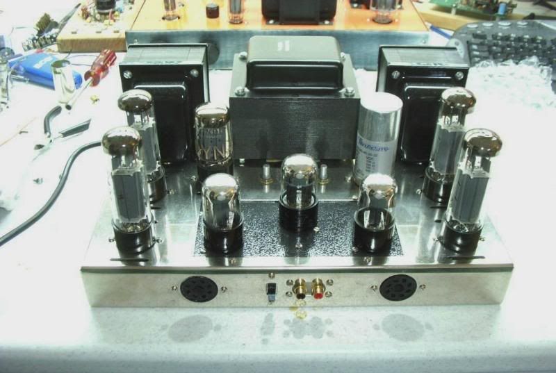
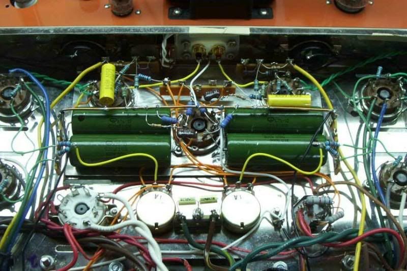
The Blackburn circuit is really easy point-to-point wired, so is the Eico HF-89 front end. The reason it looks crowded is because I laid it out around Russian K75-10 PIO caps, but they sound excellent! Here's a couple of pics of my Blackburn '70, I hate I had to sell it:(
Posted:
Fri Feb 05, 2010 5:06 pmby antiquekid3
Well, although he says the power transformer needs to be replaced, I don't think it would be a problem if it was designed to handle 8A. I might still find a small transformer to assist, though.
Those 6SN7s are bizarre! Not something I'd want to spend $80 on...I'd rather get some NOS tubes.
Terry, I might consider doing some point-to-point, if you say it's easy. I built a tube theremin using all point-to-point, so I'm up to the task.
Kyle
Posted:
Fri Feb 05, 2010 5:07 pmby antiquekid3
And another question: when I go to install the two inputs, can the outsides of the RCA plugs touch the chassis? Or do they need to be completely isolated?
Kyle