Page 1 of 1
Parts arrived today, more questions...

Posted:
Sat Jan 16, 2010 2:54 pmby xlr8
Hi folks,
I just recieved the parts to get going on my first st-70 rebuild and was wondering about moving the power switch to the front in place of the stereo/mono switch. Would there be any issues with this?
There is a diode on the new VTA board (D1). Does this diode replace the old rectifier?
In my other thread about the can cap, it was mentioned that one section should be no more than 30uf. The cans Roy sold me are 40,40,20,20. Should I strap in a 10 uf cap on that one section to compensate, or is 20uf just fine? I'll be using the Weber Copper Cap in place of the rec. tube.
I'm sure I'll have more questions as I dive in deeper, but my wife broke her left ankle this past week and has to have her foot basically bolted back onto her leg this week, so it may take longer than I had planned to do this.

Posted:
Sat Jan 16, 2010 3:41 pmby burnedfingers
I used to have one of Roy's boards so I will attempt to answer your questions.
D1 replaces to old selenium rectifier.
The cap values are fine and will cause no problems. The standard 5AR4 will handle 40-45 mfd value first cap without a problem. I usually use several 1N4007 diodes in series from pin 3 to pin 4 and from pin 5 to pin 6. Attach the AC to pin 3 and pin 5. This will allow the diodes to rectify the AC and allow the 5AR4 to slowly provide the DC to the circuit. If you are using something like a Weber Cap you can still make this modification and be able to use either a 5AR4 or the Weber cap.
If you are going to use the Weber Cap only then you can increase the 1st caps value as well as the other caps. Roy's schematic that I have shows the first cap as 40mfd followed by a choke followed by an 80mfd cap, a 20 mfd cap a 2.2K resistor and the final cap being a 30 mfd cap. You can increase these values without a problem. I use Triode Electronics power supply boards with cap values of 82 X 2/ 400 v, 390 X 2 /400, 270 x 2/ 250 and 270 X 2 /250. This gives me a first cap value of 41, 2nd value of 195, third and forth of 135mfd each. Putting the caps in series increases the voltage capabilities and halves the capacitenance. The power supply is one of the weakest points on the Dynaco. The first being the driver circuit.
One nice thing about Roy's board is the addition of the 4 bias adjustment pots. These work very nice and I have personally incorporated this idea in my Mapletree Dynaco Stereo 70 amplifier.
I did notice some heat problems associated with the plate resistors so I would recommend spacing them above the board .030-.040 to avoid any heat damage over the years.
Take care of the wife first before playing with electronics. I have found this to be helpfull over the years. I hope she recovers soon. Good luck!
Re: Parts arrived today, more questions...
Posted:
Sat Jan 16, 2010 7:50 pmby kheper
xlr8 wrote:Hi folks,
I just recieved the parts to get going on my first st-70 rebuild and was wondering about moving the power switch to the front in place of the stereo/mono switch. Would there be any issues with this?
No. Just remove the wires, then connect the outputs from the jacks to their respective driver board inputs.
There is a diode on the new VTA board (D1). Does this diode replace the old rectifier?
If you bought the "rebuild kit", the only diode I see is the one for the bias supply.

In my other thread about the can cap, it was mentioned that one section should be no more than 30uf. The cans Roy sold me are 40,40,20,20. Should I strap in a 10 uf cap on that one section to compensate, or is 20uf just fine? I'll be using the Weber Copper Cap in place of the rec. tube.
He may have sent you the incorrect part.
"CE multi section (80, 40, 30, 20)" is what is advertised with the "rebuild kit". Return what you got, and make him send you the cap, which was offered.
Posted:
Sat Jan 16, 2010 8:01 pmby burnedfingers
quote:
"CE multi section (80, 40, 30, 20)" is what is advertised with the "rebuild kit". Return what you got, and make him send you the cap, which was offered.
I suggest that you return the cap and use a Triode Electronics or similar power supply board. This is one of the best modifications you can do for the money.
Posted:
Mon Jan 18, 2010 11:22 amby mesherm
The problem with the cap boards is that they are set up to provide the C , B and A voltages used in the original ST70 along with the bias supply. Since the VTA board has the B and A plus the bias supply on the PCB itself, having a cap board with VTA board is a redundant expense.
Hook up your 40,40,20,20 with one of the 40 sections right after the copper cap, connect the remaining 40,20,20 sections together and connect the 40 to the 40+20+20 with the choke. 80 mfd is more than enough for the power section. Then also power the VTA from the 40+20+20.
Posted:
Mon Jan 18, 2010 2:34 pmby TerrySmith
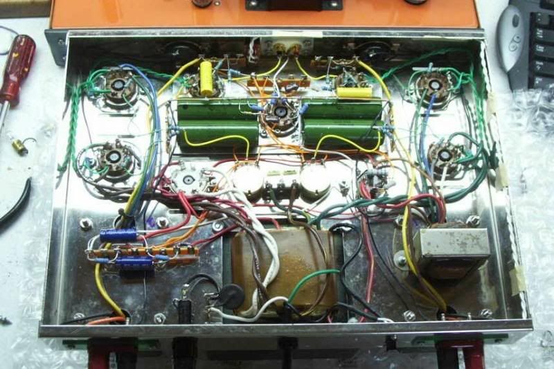
I've built three with the switch on front, route the wiring as shown and twist it tight.
Posted:
Mon Jan 18, 2010 2:49 pmby dcriner
Many amps have their power switches on the rear of the chassis. With the power transformer and the power cord at the rear, 120-V, 60-Hz power doesn't have to go from the back to the front (if the switch were there) and then to the back again. Less chance for induced hum.
Posted:
Mon Jan 18, 2010 4:38 pmby burnedfingers
quote:
Since the VTA board has the B and A plus the bias supply on the PCB itself, having a cap board with VTA board is a redundant expense.
Sorry, I do not agree. The cap values/sections are not optimum for the best sound ....my opinion. The voltage handling capability is much greater using the power supply board that has caps in series.The stiffer the supply the better the 70 sounds. Without decent sized caps the bass sound flabby at best. Properly set up the 70 can sound good. Why go to the bother of replacing the driver board only to leave the amplifier half assed done?
It isn't going to hurt not having used the bias section of the power supply board. If you don't use it now you may use it later.
My suggestion is to polish the multi cap and leave it in place so the amp looks more stock or to pull it and plug the hole. Your near by hardware store carries a chrome plated plug that will fit in the hole.
Posted:
Wed Jan 27, 2010 2:51 pmby xlr8
Ok, I have not had time to read through all of these responses yet, but I have put one of these amps together this week. Everything went well, for the most part.
I have one problem with right channel bias voltage. On the left channel, I get the proper readings and can adjust the bias with no problem. On the right channel, I get -00.1mv for some reason. I'm measuring on pins 8 and 4 on the front panel pam 1 sockets. I tried turning the amp over and measuring directly from the new resistors and get the same reading. This amp has the triode switches wired in if that could make any difference.
Any ideas on what I could have crossed or missed?
Thanks,
Jon
Posted:
Wed Jan 27, 2010 7:34 pmby Ty_Bower
I'm guessing you've somehow ended up with no voltage on the screens. Possibly due to a wiring error in your triode/pentode switch?
Posted:
Sat Jan 30, 2010 7:25 pmby mesherm
ok..I remember your post saying you had a bad OT and you subbed one in from your other ST70 and the modded one sounded great.
Beside that post that got deleted was mine asking about what tubes you were using and how you configured your power supply filter cap.
I also suggested a mod some people use where they add a polyprop film cap of 1 to 5 mfd (like a Solen Fastcap) at the B+ junction of the OTs. The theory being that the film cap will discharge quicker and improve transient response.
Posted:
Sat Jan 30, 2010 9:16 pmby xlr8
Ummmm, I'm not exactly sure what happened here. I'm not sure I understand why my posts were deleted. I appreciate the help here guys, but WTF??
Posted:
Sat Jan 30, 2010 9:54 pmby nyazzip
apparently everything from 29JAN was lost