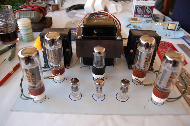
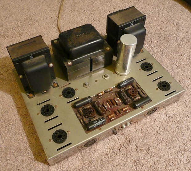
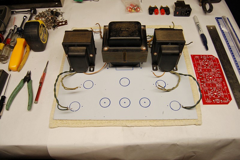
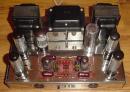
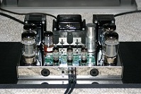
Here are a couple of pictures of the unit I'm starting with.
![]() by Wardsweb » Sat Jan 02, 2010 8:27 am
by Wardsweb » Sat Jan 02, 2010 8:27 am
![]() by Wardsweb » Sat Jan 02, 2010 9:01 am
by Wardsweb » Sat Jan 02, 2010 9:01 am
![]() by TerrySmith » Sat Jan 02, 2010 10:11 am
by TerrySmith » Sat Jan 02, 2010 10:11 am

![]() by Wardsweb » Wed Jan 13, 2010 9:28 pm
by Wardsweb » Wed Jan 13, 2010 9:28 pm
![]() by EWBrown » Thu Jan 14, 2010 10:19 am
by EWBrown » Thu Jan 14, 2010 10:19 am

![]() by Wardsweb » Thu Jan 14, 2010 12:01 pm
by Wardsweb » Thu Jan 14, 2010 12:01 pm
![]() by Wardsweb » Thu Jan 14, 2010 12:05 pm
by Wardsweb » Thu Jan 14, 2010 12:05 pm
![]() by Sal Brisindi » Sun Jan 17, 2010 10:59 am
by Sal Brisindi » Sun Jan 17, 2010 10:59 am
![]() by Wardsweb » Wed Jan 20, 2010 10:50 pm
by Wardsweb » Wed Jan 20, 2010 10:50 pm
![]() by TomMcNally » Thu Jan 21, 2010 11:03 am
by TomMcNally » Thu Jan 21, 2010 11:03 am

![]() by Sal Brisindi » Thu Jan 21, 2010 11:42 am
by Sal Brisindi » Thu Jan 21, 2010 11:42 am
![]() by Wardsweb » Thu Jan 21, 2010 12:52 pm
by Wardsweb » Thu Jan 21, 2010 12:52 pm
TomMcNally wrote:Looks sweet !
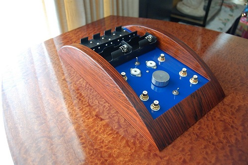
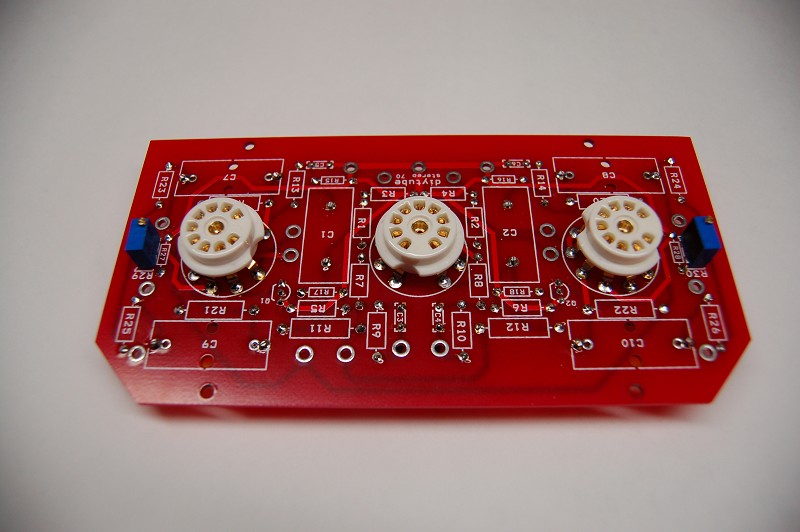
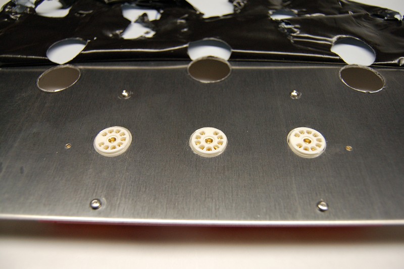
Tip: Mark the 4 corner holes of the UNBUILT board
and drill 4 holes in your chassis. Bolt the board in place.
Mark and drill the small pilot holes in the center of the
tube sockets and pots and cut your full size holes. Perfect!
Clever man that Shannon Parks ... his idea has been
used by some others since, but I think he was the first
to use that feature.
![]() by skidave » Sun Jan 24, 2010 12:37 pm
by skidave » Sun Jan 24, 2010 12:37 pm
Users browsing this forum: No registered users and 25 guests