Recently, I noticed that the right channel's sound level is very significantly less than the left's.
I changed signal tubes (12au7s), rebiased the amp, and tried different sources.
Where should I look first? Wiring? The transistor in the CCS? Coupling caps? Swap the output tubes?
I think that the problem is recent. I only noticed it after changing the 12au7 tubes about 2 days ago.
st70: sound level in one channel greatly diminished
27 posts
• Page 1 of 2 • 1, 2
st70: sound level in one channel greatly diminished
![]() by kheper » Wed Oct 01, 2008 1:56 pm
by kheper » Wed Oct 01, 2008 1:56 pm
-

kheper - KT88
- Posts: 1252
- Joined: Wed Dec 21, 2005 10:14 pm
- Location: Philly, PA
![]() by kheper » Thu Oct 02, 2008 11:47 pm
by kheper » Thu Oct 02, 2008 11:47 pm
I refreshed some solder joints on and around the right channel's 12au7 socket. This <i>seems</i> to have done the trick.
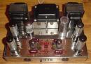
A cautionary note: I placed my st70 on a table, tried to turn the light on above the table, but the light bulb was burned out. So, I stood on the table to change the bulb, but the table's leg gave away, sending the st70 flying (or more like skiing down the inclined slope of the table). It hit a cabinet. There is now a fresh nick on one of the output transformers.
A cautionary note: I placed my st70 on a table, tried to turn the light on above the table, but the light bulb was burned out. So, I stood on the table to change the bulb, but the table's leg gave away, sending the st70 flying (or more like skiing down the inclined slope of the table). It hit a cabinet. There is now a fresh nick on one of the output transformers.
-
kheper - KT88
- Posts: 1252
- Joined: Wed Dec 21, 2005 10:14 pm
- Location: Philly, PA
![]() by TomMcNally » Fri Oct 03, 2008 8:33 am
by TomMcNally » Fri Oct 03, 2008 8:33 am
So the moral of the story is "don't stand on a table to change a light bulb if there is an ST-70 on it" ??? hah
-

TomMcNally - Darling du Jour
- Posts: 2729
- Joined: Sat Nov 19, 2005 2:19 pm
- Location: Northfield, NJ
![]() by Sal Brisindi » Sun Oct 05, 2008 10:06 am
by Sal Brisindi » Sun Oct 05, 2008 10:06 am
Or get a stronger table... Yellow_Light_Colorz_PDT_01
Congrats on finding the problem with your 70'
Sal
Congrats on finding the problem with your 70'
Sal
-
Sal Brisindi - KT88
- Posts: 374
- Joined: Thu Mar 22, 2007 5:21 am
- Location: Freehold N.J.
![]() by kheper » Thu Oct 09, 2008 1:50 pm
by kheper » Thu Oct 09, 2008 1:50 pm
Sal Brisindi wrote:Congrats on finding the problem with your 70'
Sal
This problem has not been resolved.
Further, the right output transformer runs cooler than the left.
Last night, I used the 8ohm tap on the right and the 4ohm tap on the left to gauge how much louder the left channel is relative to the right. In this configuration, the right gives a little more output than the left.
I'll swap output tubes later tonight to find out if it is the tubes or eliminate them as a possibility.
-
kheper - KT88
- Posts: 1252
- Joined: Wed Dec 21, 2005 10:14 pm
- Location: Philly, PA
![]() by Bob01605 » Sat Oct 11, 2008 12:30 pm
by Bob01605 » Sat Oct 11, 2008 12:30 pm
I wouldn't place too much significance in the left output transformer running a little warmer than the right. The right output transformer has just one EL34 in close proximity to the transformer but the left output transformer has both the left rear EL34 output tube AND the rectifier tube in close proximity (less than an inch from the transformer bell). This will decrease the thermal gradient for the left output transformer and make it more difficult for that transformer to get rid of heat.
If you have eliminated tubes and bad solder joints as a source of the problem then > What I would do to deal with your problem of unequal sound levels is check the value of every resistor and capacitor (if you have a cap tester) on the driver board on the bad channel and compare it to the value on the good channel. If you find a major difference in resistance or capacitance then you *may* have solved your problem.
Bob Latino
-
Bob01605 - Posts: 62
- Joined: Fri Jun 09, 2006 5:32 pm
- Location: New England, USA
![]() by kheper » Sat Oct 11, 2008 1:08 pm
by kheper » Sat Oct 11, 2008 1:08 pm
Bob01605 wrote:If you have eliminated tubes and bad solder joints as a source of the problem then > What I would do to deal with your problem of unequal sound levels is check the value of every resistor and capacitor (if you have a cap tester) on the driver board on the bad channel and compare it to the value on the good channel. If you find a major difference in resistance or capacitance then you *may* have solved your problem.
Bob Latino
I rearranged the tubes. The differential between the left and right channel output has diminished, but still persists.
It had to have been caused by more than one factor. Tube(s), cold solder joints, and maybe resistor values.
-
kheper - KT88
- Posts: 1252
- Joined: Wed Dec 21, 2005 10:14 pm
- Location: Philly, PA
The Solder Gremlins
![]() by EWBrown » Sun Oct 12, 2008 7:17 am
by EWBrown » Sun Oct 12, 2008 7:17 am
Doc Bottlehead and Paul Joppa have often stated that about 90% of tube amp problems can be traced back to poor solder connections, and even those that look good can still have poor contact inside.
I'd suggest carefully re-flowing each and every solder joint, and that has a fairly good probability of correcting the problem. Since moving the tubes around seems to have an effect, I'd SWAG that one or more of the tube sockets are the prime suspect, either flakey solder or perhaps the contacts have some corrosion, or are too "loose" grip on the tube pins.
One useful tip:
When soldering tube sockets, and especially octal sockets, I always insert a "junk" octal metal shell tube (make sure that it has all 8 pins) into the socket before proceeding.This gives mechanical stability to the socket contacts, which makes soldering them more easy and reliable, and prevents any solder from wicking down inside the socket and rendering it as useless. I learned this the hard way, many years ago, when building one ofmy first ST70s... For 9 pin (or any other) sockets, just insert a "plinker" before solderinmg, play it "safe". Those "useless" 19T8s and 9A8s still have a useful function even if it is not the original intended purpose Yellow_Light_Colorz_PDT_06 Yellow_Light_Colorz_PDT_04
HTH
/ed B
Real Radios Glow in the Dark
-

EWBrown - Insulator & Iron Magnate
- Posts: 6389
- Joined: Wed Mar 19, 2003 6:03 am
- Location: Now located in Clay County, NC !
Re: The Solder Gremlins
![]() by kheper » Tue Oct 14, 2008 4:09 pm
by kheper » Tue Oct 14, 2008 4:09 pm
EWBrown wrote:Doc Bottlehead and Paul Joppa have often stated that about 90% of tube amp problems can be traced back to poor solder connections, and even those that look good can still have poor contact inside.
I'd suggest carefully re-flowing each and every solder joint, and that has a fairly good probability of correcting the problem. Since moving the tubes around seems to have an effect, I'd SWAG that one or more of the tube sockets are the prime suspect, either flakey solder or perhaps the contacts have some corrosion, or are too "loose" grip on the tube pins.
One useful tip:
When soldering tube sockets, and especially octal sockets, I always insert a "junk" octal metal shell tube (make sure that it has all 8 pins) into the socket before proceeding.This gives mechanical stability to the socket contacts, which makes soldering them more easy and reliable, and prevents any solder from wicking down inside the socket and rendering it as useless. I learned this the hard way, many years ago, when building one ofmy first ST70s... For 9 pin (or any other) sockets, just insert a "plinker" before solderinmg, play it "safe". Those "useless" 19T8s and 9A8s still have a useful function even if it is not the original intended purpose Yellow_Light_Colorz_PDT_06 Yellow_Light_Colorz_PDT_04
HTH
/ed B
I reflowed most of the solder connections, especially on the output sockets and the output transformers. No difference. The right channel remains low in output. The problem is either linked to components on the driverboard or the output transformer.
I forgot to pull the driver tubes when refreshing the joints on their sockets. I do not think that I damaged them.
-
kheper - KT88
- Posts: 1252
- Joined: Wed Dec 21, 2005 10:14 pm
- Location: Philly, PA
![]() by Ty_Bower » Tue Oct 14, 2008 4:31 pm
by Ty_Bower » Tue Oct 14, 2008 4:31 pm
Get out a printed copy of the circuit board diagram and the parts list. Go through with your ohmmeter and measure every resistor on the board. Cross them off as you verify each is correct. It should go without saying, but the amp needs to be powered off while measuring the resistors. You may as well pull out the tubes, too. A few resistors might be impossible to measure while in the circuit, since they may be tied to ground in more than one place.
While you have your ohmmeter out, measure the DC resistance of the primary side of each output transformer. Measure from plate to plate, and also from each plate to the center (red) lead. For Dynaco transformers, it is normal for the measurement from plate lead to center lead to differ on each side of the same transformer. The measurements of the left channel transformer should be similar to the right channel.
Post any measurements which look suspicious. If all the ohm readings appear normal, then it will be time to move on to working voltage readings.
-

Ty_Bower - KT88
- Posts: 1494
- Joined: Wed Mar 21, 2007 2:50 pm
- Location: Newark, DE
![]() by kheper » Tue Oct 14, 2008 6:09 pm
by kheper » Tue Oct 14, 2008 6:09 pm
Ty_Bower wrote:Get out a printed copy of the circuit board diagram and the parts list. Go through with your ohmmeter and measure every resistor on the board. Cross them off as you verify each is correct. It should go without saying, but the amp needs to be powered off while measuring the resistors. You may as well pull out the tubes, too. A few resistors might be impossible to measure while in the circuit, since they may be tied to ground in more than one place.
While you have your ohmmeter out, measure the DC resistance of the primary side of each output transformer. Measure from plate to plate, and also from each plate to the center (red) lead. For Dynaco transformers, it is normal for the measurement from plate lead to center lead to differ on each side of the same transformer. The measurements of the left channel transformer should be similar to the right channel.
Post any measurements which look suspicious. If all the ohm readings appear normal, then it will be time to move on to working voltage readings.
I had the amp on so I thought I'd take a few preliminary voltage measurements.
J13= 0V same a left channel
J21= 40.3V close to left channel
J22= 36.5V same as left channel
J23= 37.4V very close to left channel
Right 12UA7:
1= 240V close to left channel
2= 0V same as left channel
3= 10V same as left channel
4= 3.06Vac (left channel = 3.23Vac)
5= 3.06Vac (left channel = 3.23Vac)
6= 245V very close to left channel
7= 0V same as left channel
8= 10V same a left channel
9= 3.23Vac (left channel = 3.08Vac)
-
kheper - KT88
- Posts: 1252
- Joined: Wed Dec 21, 2005 10:14 pm
- Location: Philly, PA
![]() by kheper » Wed Oct 15, 2008 3:37 am
by kheper » Wed Oct 15, 2008 3:37 am
Ty_Bower wrote:Looks normal. What do you see at the plate of each side of the 12AX7 (1 & 6)? How about the cathode of each half of the 12AX7 (3 & 8)?
Resistance values for the below are identical or close on both the right and the left channels, but some do not jive with those given in the manual:
J13= 10k
J21
J22
J23
right 12UA7:
1
2= 1M
3= 223k
4
5
6
7
8= 217k
9
12ax7:
1= 186V
3= 1.2V
6= 184V
8= 7.5V (this voltage is not stable)
The values of the resistors on the driverboard around both 12au7s in circuit are close or identical.
I substituted some Stromberg Carlson branded, RCA 5963 tubes for the 12AU7s. They excel in definition.
-
kheper - KT88
- Posts: 1252
- Joined: Wed Dec 21, 2005 10:14 pm
- Location: Philly, PA
![]() by kheper » Wed Oct 15, 2008 9:14 pm
by kheper » Wed Oct 15, 2008 9:14 pm
Ty_Bower wrote:kheper wrote:12ax7:
...
8= 7.5V (this voltage is not stable)
Your problem is not far from here. Do you have a spare 12AX7 (or 5751 or 7025) to swap?
Yes, but I was saving it as the last resort. It is from an old, old, old Dynaco FM-3.
Voltage on pin 3 and 8 of the Dynaco12ax7 is 3.24V.
-
kheper - KT88
- Posts: 1252
- Joined: Wed Dec 21, 2005 10:14 pm
- Location: Philly, PA
27 posts
• Page 1 of 2 • 1, 2
Who is online
Users browsing this forum: No registered users and 93 guests