Tube numbering convention for ST-70
7 posts
• Page 1 of 1
Tube numbering convention for ST-70
![]() by rockable » Sat May 03, 2008 7:31 am
by rockable » Sat May 03, 2008 7:31 am
What is the tube numbering system for ST-70's. I know that guitar amps are V1 on the right and the numbering progresses to the left. I have no clue of what Dynaco used. Thanks.
-

rockable - Posts: 49
- Joined: Thu Apr 10, 2008 7:02 pm
- Location: Greensboro, NC
![]() by burnedfingers » Sat May 03, 2008 9:02 am
by burnedfingers » Sat May 03, 2008 9:02 am
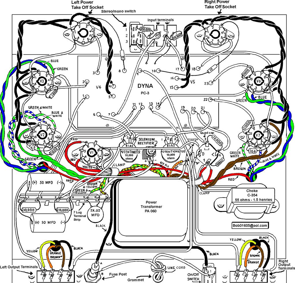
Facing the driver board. Rectifier is V1, El34 closest to rectifier and or the output transformer is V2, and V3 is closest to the driver board on that side. Other side (right) is V6 by the driver board and V7 by the choke or power supply capacitor. V4 and V5 must be the 7199's. I would guess that V4 would be on the left side as you faced the driver board but I cannot tell from any picture I have found so far.
Last edited by burnedfingers on Sat May 03, 2008 9:09 am, edited 1 time in total.
- burnedfingers
- KT88
- Posts: 640
- Joined: Mon Sep 05, 2005 6:38 am
ST-70 tube numbers
![]() by Bob01605 » Sat May 03, 2008 9:08 am
by Bob01605 » Sat May 03, 2008 9:08 am
Rockable,
On the ST-70 V1 is the GZ34 rectifier tube
V2 and V3 are the two LEFT channel tubes output tubes - V3 is the tube closest to the FRONT of the chassis
V4 is the LEFT channel 7199 and V5 is the RIGHT channel 7199 tube.
V6 and V7 are the two RIGHT channel output tubes - V6 is the tube closest to the FRONT of the chassis
The power takeoff sockets as far as I know were not given a number.
Check the link listed below for the original ST-70 pictorial with some wiring colored in by me.
http://i9.photobucket.com/albums/a78/Bo ... r_1024.jpg
Bob Latino
-
Bob01605 - Posts: 62
- Joined: Fri Jun 09, 2006 5:32 pm
- Location: New England, USA
![]() by mesherm » Fri May 09, 2008 11:48 am
by mesherm » Fri May 09, 2008 11:48 am
In the pictorial, the + end of the bias caps appear to me to be grounded. There is a wire from the terminal strip the + ends are soldered to that connects to the center of the dual 0.02uf ceramic cap and then runs on to the common ground lug.
Mike's N-1 Rule: When looking for N number of components to finish a job, you have a 95% chance of only finding N-1 of them.
-

mesherm - KT88
- Posts: 1232
- Joined: Fri Aug 27, 2004 10:33 pm
- Location: Alvin Texas
7 posts
• Page 1 of 1
Who is online
Users browsing this forum: No registered users and 96 guests