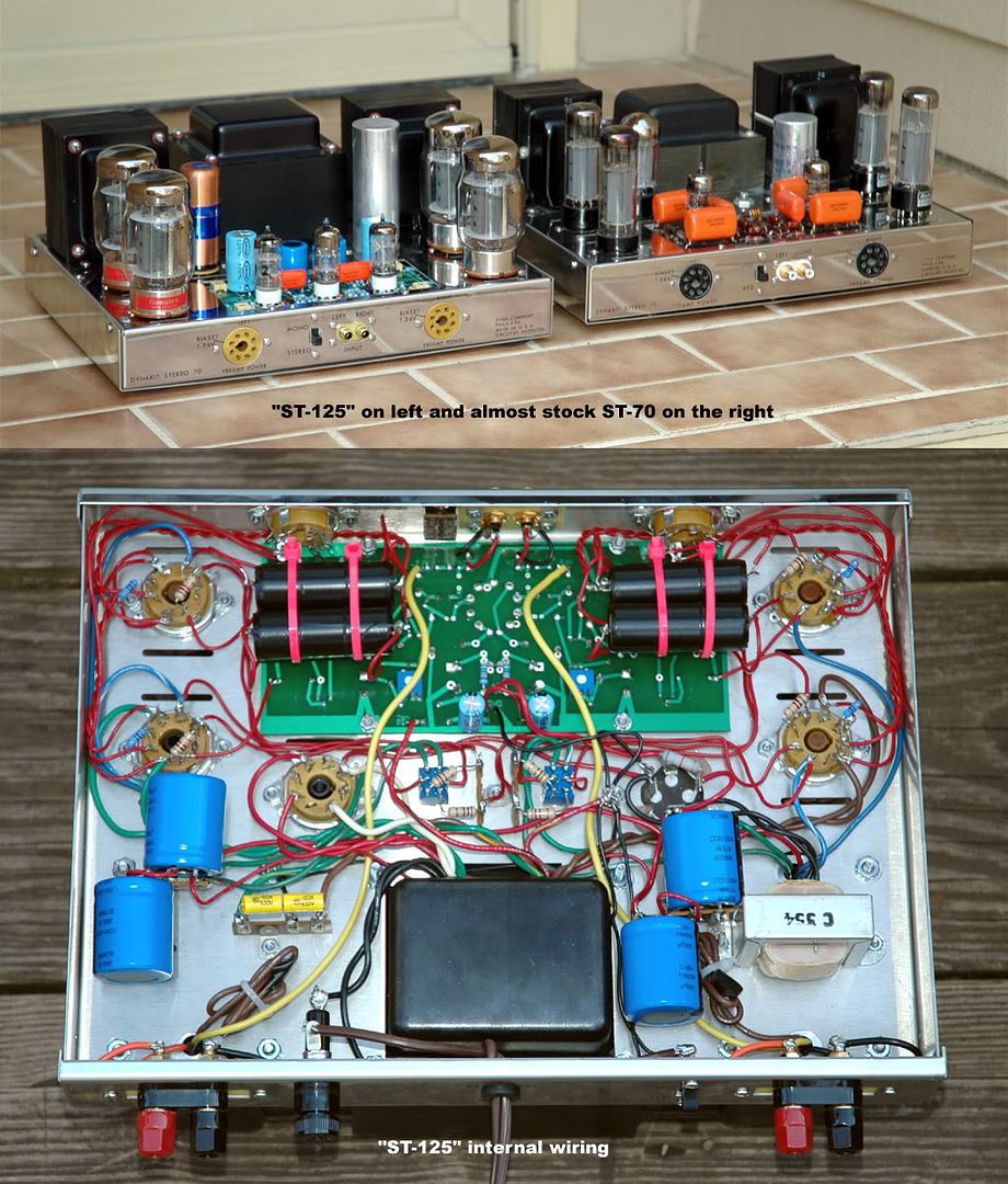
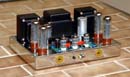
Two Mark III's on a Stereo 70 chassis ? Well I though I would give it a shot and attempt to create a 60-65 watt per channel amp (an ST-125 ??) on a Dynaco ST-70 chassis. It seems to have worked out OK.
The power transformer instead of having the 360-0-360 volt secondaries of a normal PA-060 power transformer has 420-0-420 secondaries and is rated at 425 milliamps. A normal PA-060 has a stack lamination of about 1 1/2 - 1 5/8" while this power tranny has a stack lamination of a little over 2.7 inches. The new power transformer puts out about 500 volts on the first section of the quad cap and about 485 volts on the plates of the output tubes.
The output transformers are interleaved/layer wound with M6 grain oriented laminations and are 3 7/8" tall, 3 1/4" wide and 3 1/8" deep (about 1/2" taller, 3/8" wider and 1/4" deeper than a stock A-470 output transformer). Each output transformer weighs about 2 pounds more than a stock A-470 output transformer.
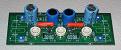
A Dynakitparts (80, 40, 30, 20 @ 550 volt) quad cap was used for power storage but was supplemented on the second section of the cap by two banks of 195 Mfd @ 800 volt caps mounted on terminal strips. I am measuring about 495 Mfd on the second section of the quad cap with my cap meter. I am presently using a Weber WZ68 Copper cap solid state rectifier which is equal to two GZ34's and is rated at 450 milliamps. The Weber has a short built in delay of about 2 seconds before it applies the high voltage and gives a higher B+ than any of the Mullard GZ34's that I tried in there.
A VTA driver board was used with some minor modifications. Instead of a 2200 ohm resistor to drop down the B+ to the driver board down to 400 - 410 volts, a 6800 ohm resistor was needed to drop the B+ about 70 volts. .27 Mfd @ 750 volt Vitamin Q coupling caps are used. These caps have the outside of the case conductive so I wrapped them in tape. The triode/pentode switches that I usually put in these amps have taken the extra voltage in stride. I flipped each one back and forth about 100 times while the amp was playing with no problems.
The amp is dead quiet, plays very well and is noticeably more dynamic at higher volumes than a comparable VTA board driven ST-70. I am presently running a matched quad of the new Genalex Gold Lion KT88's in this amp. An A and B comparison with my pair of Mark III's shows pretty much equal power with maybe a slight nod (according to my friend Paul who listened with me) at higher volumes to the newer amp built on the ST-70 chassis . This was due undoubtedly to the better power supply on the newer amp.
Photo of this amp and internal wiring at link below ...
http://i9.photobucket.com/albums/a78/Bo ... osite2.jpg
Bob Latino
Dynaco "ST-125"? - Two "Mark III's" on a
14 posts
• Page 1 of 1
Dynaco "ST-125"? - Two "Mark III's" on a
![]() by Bob01605 » Sat Apr 26, 2008 8:10 am
by Bob01605 » Sat Apr 26, 2008 8:10 am
-
Bob01605 - Posts: 62
- Joined: Fri Jun 09, 2006 5:32 pm
- Location: New England, USA
![]() by burnedfingers » Sat Apr 26, 2008 9:34 am
by burnedfingers » Sat Apr 26, 2008 9:34 am
Bob,
It looks very nice Yellow_Light_Colorz_PDT_01
I have some questions....
Is the VTA driver board capable of providing roughly around 100 volts peak to peak that would be needed in order to provide adequate drive voltage for the KT88's? I don't have one to measure at this time but feel it may fall short.
Have you ever considered using a quad pole double throw switch to switch from standard to triode mode. It might be a cleaner look.
Is there a possibility of using a SDS cap board under the chassis?
What power transformer did you use?
Thanks,
Joe
- burnedfingers
- KT88
- Posts: 640
- Joined: Mon Sep 05, 2005 6:38 am
![]() by Bob01605 » Sat Apr 26, 2008 1:24 pm
by Bob01605 » Sat Apr 26, 2008 1:24 pm
Hi,
Roy Mottram who designed the VTA driver board tells me it will drive a KT88 based amp just fine. I honestly don't know what the voltage is peak to peak on the VTA board. With Roy's guidance, some changes were made on the board to better deal with driving KT88's. I don't want to say what the changes are because I am still tinkering with the driver board components.
Because the two 3/8 inch holes in the center of the chassis are not used for the bias pots - It is a logical place to place the two triode/pentode switches. You COULD use a quad pole switch but where to mount it may be an issue. By have separate switches on each channel, you can vertically biamp with one amp on each stereo channel and run (if you are so inclined to do so) the woofer section in pentode and the tweeter section in triode. I have done this and the slight reduction in the triode power level is not even noticeable.
Yes - you could use the SDS ST-70 board in this amp in place of the caps I used in this prototype amp but you must change some of the caps to a slightly higher voltage rating. C1 and C2 are OK (together in series they are 800 volt rated) but C3 through C8 must be upgraded to a higher voltage.
The power transformer is one that I had custom made for me for this prototype amp by one of my transformer vendors.
Bob Latino
-
Bob01605 - Posts: 62
- Joined: Fri Jun 09, 2006 5:32 pm
- Location: New England, USA
![]() by burnedfingers » Sat Apr 26, 2008 5:19 pm
by burnedfingers » Sat Apr 26, 2008 5:19 pm
Because the two 3/8 inch holes in the center of the chassis are not used for the bias pots - It is a logical place to place the two triode/pentode switches. You COULD use a quad pole switch but where to mount it may be an issue. By have separate switches on each channel, you can vertically biamp with one amp on each stereo channel and run (if you are so inclined to do so) the woofer section in pentode and the tweeter section in triode. I have done this and the slight reduction in the triode power level is not even noticeable.
Bob,
I generally go to the hardware store and purchase two chrome plated plugs to go into the bias control holes. I enlarge the center hole to accept the switch.
When I triamp a system I generally use one complete amplifier for high frequency, one for mids, and one for low frequency. If I biamp I will use one complete amplifier to drive the lows and one for the highs. This practice is based on running and repairing large commercial systems. It is less confusing to dedicate one amplifier instead of splitting the amplifier and having half do lows and half do highs and having a second amplifier split the same way. The same thing can be accomplished with less confusion. But I guess to each his own.
- burnedfingers
- KT88
- Posts: 640
- Joined: Mon Sep 05, 2005 6:38 am
VTA 70 board driving KT88s
![]() by tubes4hifi » Sun Apr 27, 2008 1:04 am
by tubes4hifi » Sun Apr 27, 2008 1:04 am
BurnedFingers - you're probably the one that asked me this question via email a couple days ago . . . I had to tell you it's been over 10 years since I last made any measurements on this board, after all, it's been the best thing anyone has used in the past 20 years (well IMHO and about a thousand satisfied customers . . .)
If memory serves me correctly it will easily swing 100v p-p and it may even be as high as 200v p-p.
This is a simple measurement that can be done with an o'scope and a signal generator. Put in about 200mv p-p on the input, and hook up the scope to the outputs of the PCB, and you can increase the input until the outputs start clipping.
But for sure I can tell you this circuit stock will drive a QUAD set of KT88's on EACH channel, and with 12BH7s I'm pretty sure it will drive 6 or 8 KT88s on each channel.
The circuit as I've mentioned dozens of times before is a copy of the same circuit VTL used in the late 80s on all of their amplifiers, I just adapted it to fit into an ST70 and use one tube for a voltage amp instead of 2 tubes. The design of the phase splitter is what makes it so good.
Several years ago I built a couple of mono amps using this circuit to drive a six pack of EL34 outputs, essential a clone of the Cary SixPac amp, but using my own circuit.
Both Bob and myself have built several amps using this PCB to drive KT88s, so we know it works very well and very reliably.
Roy www.tubes4hifi.com
"the path of least resistance is thru a vacuum"
-
tubes4hifi - Posts: 113
- Joined: Thu Jan 15, 2004 12:52 pm
- Location: Tacoma, WA
![]() by burnedfingers » Sun Apr 27, 2008 7:20 am
by burnedfingers » Sun Apr 27, 2008 7:20 am
If memory serves me correctly it will easily swing 100v p-p and it may even be as high as 200v p-p.
Thats all I was wanting to know when I emailed you asking for the information. Unfortunately I do not have my Dynaco with your board handy to measure. Yes, I do understand how to make the measurement. Generally I make a measurement and keep it on file for future reference but this time I didn't. I have a project in the works and I am looking for a board to suit my purpose.
Thats all I was wanting to know when I emailed you asking for the information. Unfortunately I do not have my Dynaco with your board handy to measure. Yes, I do understand how to make the measurement. Generally I make a measurement and keep it on file for future reference but this time I didn't. I have a project in the works and I am looking for a board to suit my purpose.
- burnedfingers
- KT88
- Posts: 640
- Joined: Mon Sep 05, 2005 6:38 am
Re: Biamping with Dynaco ST-70's
![]() by Bob01605 » Sun Apr 27, 2008 10:04 am
by Bob01605 » Sun Apr 27, 2008 10:04 am
Burnedfingers,
Regarding the point you made in your statement > "If I biamp I will use one complete amplifier to drive the lows and one for the highs. This practice is based on running and repairing large commercial systems. It is less confusing to dedicate one amplifier instead of splitting the amplifier and having half do lows and half do highs and having a second amplifier split the same way. The same thing can be accomplished with less confusion. But I guess to each his own."
From a two channel hi-fi point of view and from personal listening to VTA board driven ST-70's this, IMHO, is not the best way to go. By vertical biamping (one ST-70 on each stereo channel) you allow TWO power transformers and TWO quad caps to deal with the power sucking low end. In a horizontal biamp situation (with one amp powering both woofer sections) only one ST-70 power transformer and one quad cap are handling the woofer section which always pulls much more current out of the amp than the tweeter section.
Another reason is that in a vertical biamp situation you have total channel separation at least within the amp section which ususally translates to a larger soundstage and the seemingly "more separation" of the stereo channels. This is one of the reason that some people favor separate monoblock amps for their stereo system. I have listened to biamped ST-70's a number of times in both a horizontal and a vertical biamped configuration and have always preferred the improved soundstaging and other positive characterstics of the vertical method - again - at least with Dynaco ST-70's on a two channel stereo system.
Bob Latino
-
Bob01605 - Posts: 62
- Joined: Fri Jun 09, 2006 5:32 pm
- Location: New England, USA
![]() by burnedfingers » Sun Apr 27, 2008 12:07 pm
by burnedfingers » Sun Apr 27, 2008 12:07 pm
Bob,
I guess that if you have to split the load one low and one high on one amplifier that would seem to indicate that the power supply is somewhat anemic. A properly designed amplifier with a hefty power supply wouldn't have a problem running the right and left channel of low frequency at the same time in my opinion. I guess I wouldn't ask a small amplifier like a stereo 70 to attempt to handle the bass needs of a serous system. I would opt for a larger tube amplifier or go straight to some serious solid state power but that me.
I guess that if you have to split the load one low and one high on one amplifier that would seem to indicate that the power supply is somewhat anemic. A properly designed amplifier with a hefty power supply wouldn't have a problem running the right and left channel of low frequency at the same time in my opinion. I guess I wouldn't ask a small amplifier like a stereo 70 to attempt to handle the bass needs of a serous system. I would opt for a larger tube amplifier or go straight to some serious solid state power but that me.
- burnedfingers
- KT88
- Posts: 640
- Joined: Mon Sep 05, 2005 6:38 am
![]() by Bob01605 » Sun Apr 27, 2008 5:29 pm
by Bob01605 » Sun Apr 27, 2008 5:29 pm
burnedfingers wrote:Bob,
I guess that if you have to split the load one low and one high on one amplifier that would seem to indicate that the power supply is somewhat anemic. A properly designed amplifier with a hefty power supply wouldn't have a problem running the right and left channel of low frequency at the same time in my opinion. I guess I wouldn't ask a small amplifier like a stereo 70 to attempt to handle the bass needs of a serous system. I would opt for a larger tube amplifier or go straight to some serious solid state power but that me.
The power supply on the ORIGINAL ST-70 WAS anemic. 20 Mfd on the second section of the quad cap which powers the TWO output transformers was way low! Upgrading an ST-70 from the stock 30, 20, 20, 20 quad cap to the CE Distribution 80, 40, 30, 20 quad cap OR the SDS cap board makes a big difference in how the amp plays at higher volumes.
I think what you are doing is attempting to make a straight comparison between your experience in dealing with larger 200+ watt commercial systems and a two channel ST-70 which has a relatively modest 35 WPC watt output. The ST-70 will always come out as the loser in any such comparison. Within its power range and if set up properly with quality upstream components, the Dynaco ST-70 can give a very rewarding musical experience to most listeners ...
Bob Latino
-
Bob01605 - Posts: 62
- Joined: Fri Jun 09, 2006 5:32 pm
- Location: New England, USA
![]() by jeffdavison » Sun Apr 27, 2008 8:35 pm
by jeffdavison » Sun Apr 27, 2008 8:35 pm
Posted this build awhile back... Complete dual mono on a ST-70 Chassis.
Dual Toroids and Edcor 60 watt opts.. Dr Lloyds "Special Red" driver.
http://s130.photobucket.com/albums/p280 ... =slideshow
http://s130.photobucket.com/albums/p280 ... rent=7.jpg
JD
Dual Toroids and Edcor 60 watt opts.. Dr Lloyds "Special Red" driver.
http://s130.photobucket.com/albums/p280 ... =slideshow
http://s130.photobucket.com/albums/p280 ... rent=7.jpg
JD
- jeffdavison
- Posts: 143
- Joined: Tue Nov 21, 2006 10:22 am
- Location: Suwanee, Georgia USA
![]() by burnedfingers » Mon Apr 28, 2008 5:01 am
by burnedfingers » Mon Apr 28, 2008 5:01 am
I think what you are doing is attempting to make a straight comparison between your experience in dealing with larger 200+ watt commercial systems and a two channel ST-70 which has a relatively modest 35 WPC watt output. The ST-70 will always come out as the loser in any such comparison. Within its power range and if set up properly with quality upstream components, the Dynaco ST-70 can give a very rewarding musical experience to most listeners ...
Well Bob what I am trying to say is if the power supply is stiff enough both channels of low frequency can be driven by one amplifier instead of your need to run one high frequency channel and one low off of one amplifier. Properly designed and setup no difference can be heard from running both channels of low frequency off of one amplifier. I've done it before and blind listening tests confirmed it.
My Mapletree (Dr. Lloyds special Red October driver board) coupled with a very modified stiff power supply driving 6BG6GA's for output tubes supplies the low end and will exceed the capabilities of my Quicksilver mono block KT88 60 watt amps on the low end. So, low end is easy enough to accomplish even with 35 watt Dynaco Stereo 70's. A modified Stereo 70 in triode mode runs my high frequency when I feel a need to biamp.
For the record....I generally play with 55-60K worth of power in my systems and I surely know what to expect from lower powered systems.
- burnedfingers
- KT88
- Posts: 640
- Joined: Mon Sep 05, 2005 6:38 am
![]() by mesherm » Mon Apr 28, 2008 2:05 pm
by mesherm » Mon Apr 28, 2008 2:05 pm
Nice amp Bob.
I have something similar although its limited to 35 watts per channel by the OPTs . It uses a PA-060S upgrade power trannie I got from Triode while Uncle Ned was still there and Hammond 1650Gs (no UL taps). It also uses KT88s in triode mode and Roy's VTA driver. I also used the same CopperCap. I should pull it out of the closet and measure the power output some day.
I've used Roy's VTA with many amps and never had a problem obtaining enough drive voltage. I don't see why it couldn't drive PPP KT88s.
Mike's N-1 Rule: When looking for N number of components to finish a job, you have a 95% chance of only finding N-1 of them.
-

mesherm - KT88
- Posts: 1232
- Joined: Fri Aug 27, 2004 10:33 pm
- Location: Alvin Texas
![]() by EWBrown » Tue Apr 29, 2008 6:32 am
by EWBrown » Tue Apr 29, 2008 6:32 am
I'm workig on a similar KT88 based "ST100", I bought the chassis plate, trafomatic trannies and modified VTA driver board from Roy, this one is set up for two GZ-34s basically connected in parallel, or SS rectification could be used, as needed. THis all fits onto a 17 X 10 top plate, which sits atop an inverted Hammond 17X 10 X 3 chassis (which will be "hidden" with a decorative wood base surrounding it).
It has two C354 chokes, one set up one for each channel.
Which brings me to one question, what is your total B+ current - that single C354 must be getting pushed pretty hard...
So far the only real "progress" on this project is that I enlarged the holes in the chassis plate, in order to allow more room and clearance for the trafomatics' leads to safely penetrate to under the chassis.
With the big move, etc, occuring, most of my major projects are now on "hold" until I get settled in down there.
/ed B in NH / NC
Real Radios Glow in the Dark
-

EWBrown - Insulator & Iron Magnate
- Posts: 6389
- Joined: Wed Mar 19, 2003 6:03 am
- Location: Now located in Clay County, NC !
![]() by Bob01605 » Tue Apr 29, 2008 11:00 am
by Bob01605 » Tue Apr 29, 2008 11:00 am
Ed,
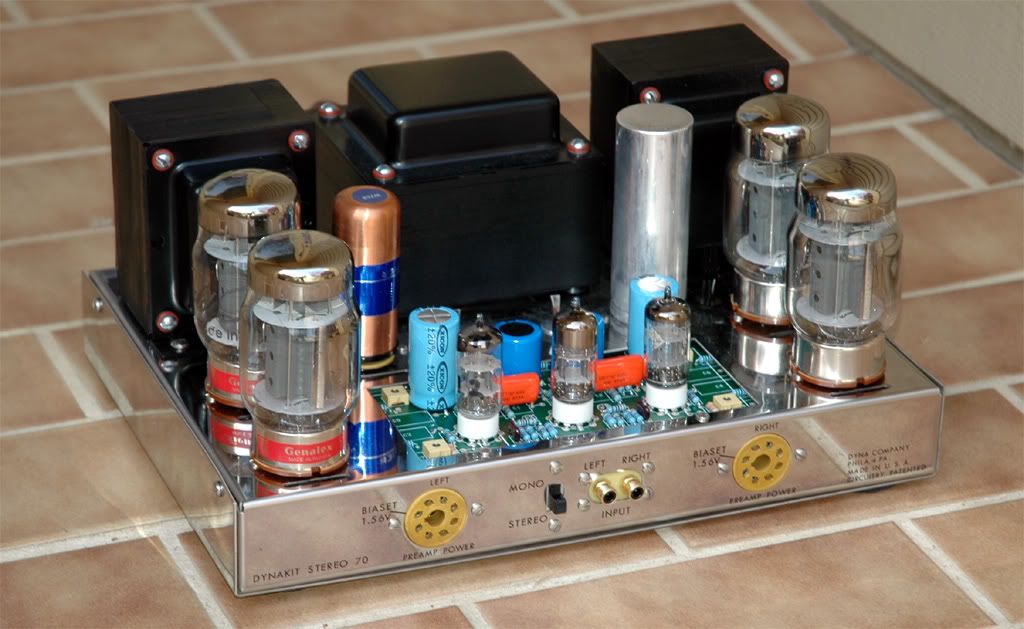
As it states above in my first post - I am getting about 485 volts or so on the plates of the output tubes (pin 3). The first section of the quad cap is about 500-505 volts depending on my house current at the time I measure the voltage. The second section after the choke is in the 485 volt range.
The two GZ34's that you mention are a good idea. The Weber solid state cap is (supposedly) equal to two GZ34's. It gives a higher B+ than any GZ34 TUBE that I tried in there.
Your KT88 based amp sounds interesting - with the larger 17 X 10 inch chassis you have more "real estate" to work in than the standard 13 X 9 1/2" ST-70 chassis. I should mention that one of the criteria for making up this amp was that it had to fit in a standard Dynaco ST-70 chassis.
Your point about the single C-354 being pushed hard is well taken. I am watching that choke carefully since it is only rated at 200 milliamps but is undoubtedly passing more current than that in this amp.
A closer look at this amp at the link below ..
http://i9.photobucket.com/albums/a78/Bo ... ST-125.jpg
Bob Latino
-
Bob01605 - Posts: 62
- Joined: Fri Jun 09, 2006 5:32 pm
- Location: New England, USA
14 posts
• Page 1 of 1
Who is online
Users browsing this forum: No registered users and 74 guests