Has anyone altered the Diytube board for
individual tube bias with 4 wirewound pots?
Any good hints on how to proceed?
I have an open frame power transformer. It will
just fit inside the chassis, mounted horizontally.
Will this generate less EMI, than mounted
vertically on top of the chassis?
BTW. I got some NOS GE 12AU7A tubes.
They sound very bassy, but carry an annoying
amount of low frequency distortion. Best to
stick with Tung-sol or RCA 12AU7s.
Individual tube bias
15 posts
• Page 1 of 1
Individual tube bias
![]() by kheper » Tue Mar 11, 2008 1:15 pm
by kheper » Tue Mar 11, 2008 1:15 pm
-

kheper - KT88
- Posts: 1252
- Joined: Wed Dec 21, 2005 10:14 pm
- Location: Philly, PA
![]() by burnedfingers » Fri Apr 11, 2008 5:03 am
by burnedfingers » Fri Apr 11, 2008 5:03 am
I don't have this board on either of my two Dynaco sereo 70 amplifiers but I can tell you how to do it from looking at the stock stereo 70 board.
With the stereo 70 schematic as a reference... Find the point where the bias is connected. Pull that resistor out (270K) from on top of the board and re-install with one end at the junction of the #22 eyelet. Now do the same for the other resistor and install it at the junction of the #23 eyelet.
This will leave one end of the resistor hanging down on each side. Connect the center of each new bias pot to this point. One bias pot to the resistor at point 22 and the other bias pot at the resistor at point 23.
Now take the 15.6 ohm resistor off and set it to the side. Install a new resistor (10 ohm) at each output tubes pin 8 to ground. Solder a wire from this point and solder it to an open terminal on the front octal socket.
Do this for each output tube. Note* If you do not wish to solder to the octal sockets on the front you will have to figure another place in which to check your bias.
Now, you will do this for both channels and remember to turn the bias down all the way before turning on the amplifier to set the bias for the first time.
- burnedfingers
- KT88
- Posts: 640
- Joined: Mon Sep 05, 2005 6:38 am
![]() by burnedfingers » Fri Apr 11, 2008 5:58 am
by burnedfingers » Fri Apr 11, 2008 5:58 am
If this is the diytube board that uses a 12ax7 input tube and a 12au7 tube.
The resistors you need to work with will be R24, and R26 for one channel and R23, and R25 for the other channel. I haven't seen this board but I would suggest doing the same thing as one would do on a stereo 70 stock board as I suggested in the above post. The output from the single bias pot center terminal/wiper supplies bias to the junction of R24 and R26 and on the other channel it would be R23 and R25. You would be hanging the resistor from the bottom of the board as outlined above post and suppling the bias to the unconnected end of the resistor. The original pot one side to one resistor and the new pot to the other resistor and the same for the other channel.
Hope this helps.. :)
- burnedfingers
- KT88
- Posts: 640
- Joined: Mon Sep 05, 2005 6:38 am
![]() by Ty_Bower » Fri Apr 11, 2008 9:56 am
by Ty_Bower » Fri Apr 11, 2008 9:56 am
Doesn't the ST70 board use the two pots on the chassis to set the bias voltage for each side, then R29 or R30 to balance each half of the push/pull pair? This really is a better way to set the bias.
If you use a separate pot dedicated to each tube, then tweaking one tube will make the other move a little bit. You can spend forever going back and forth between the two trying to get it perfect. With the balance pot, it isn't nearly as time consuming to get it right.
If you use a separate pot dedicated to each tube, then tweaking one tube will make the other move a little bit. You can spend forever going back and forth between the two trying to get it perfect. With the balance pot, it isn't nearly as time consuming to get it right.
-

Ty_Bower - KT88
- Posts: 1494
- Joined: Wed Mar 21, 2007 2:50 pm
- Location: Newark, DE
![]() by burnedfingers » Fri Apr 11, 2008 3:52 pm
by burnedfingers » Fri Apr 11, 2008 3:52 pm
Quote:
If you use a separate pot dedicated to each tube, then tweaking one tube will make the other move a little bit. You can spend forever going back and forth between the two trying to get it perfect. With the balance pot, it isn't nearly as time consuming to get it right.
--------------------------------------------------------------------------------
I will have to disagree with you on this. It takes me two adjustments to set the bias point I want. I don't see the extra tweaking as a problem. I have converted ALL my amplifiers to individual bias and eliminated the need to have matched tubes. As we all know matched tubes don't stay perfectly matched over their lifetime. kheper expressed interest in individual tube bias and this is why I posted a response. The modification is straight forward and can be done by anyone in less than 1/2 hr.
[/quote]
- burnedfingers
- KT88
- Posts: 640
- Joined: Mon Sep 05, 2005 6:38 am
![]() by skidave » Tue Dec 30, 2008 10:53 am
by skidave » Tue Dec 30, 2008 10:53 am
I was reviewing this older post about individual bias and what wattage potentiometer could be used if you went to individual tube bias? I would like to use four new pots...but finding a size to fit obscurely somewhere in the chassis(based on a 2 watt rating) is almost impossible. The wattage of the pot should / could be less because it is for one tube only.
I looked at a Velleman schematic of one of their paralleled EL34 amps and they are using a trimmer type potentiometer. The wattage is not specified, but I'm guessing a half watt. I think the VTA board uses half watt trimmers as well...
Any thoughts?
Thanks,
Dave
I looked at a Velleman schematic of one of their paralleled EL34 amps and they are using a trimmer type potentiometer. The wattage is not specified, but I'm guessing a half watt. I think the VTA board uses half watt trimmers as well...
Any thoughts?
Thanks,
Dave
-
skidave - Posts: 141
- Joined: Fri Jan 06, 2006 2:04 pm
- Location: York, PA
![]() by Ty_Bower » Tue Dec 30, 2008 11:07 am
by Ty_Bower » Tue Dec 30, 2008 11:07 am
In my opinion, a 2 watt pot is overkill. This is the negative bias circuit - there is virtually no current flow here at all.
On the other hand, a high reliability pot would be a desirable thing. If the bias supply goes out, the tubes will cook to death within minutes. Bad things will probably happen to the rectifier and possibly the output transformers, too.
I'd go for a quality hot molded carbon (PEC) or conductive plastic pot. Skip the cheap carbon pots.
"It's a different experience; the noise occlusion, crisp, clear sound, and defined powerful bass. Strong bass does not corrupt the higher frequencies, giving a very different overall feel of the sound, one that is, in my opinion, quite unique."
-
Ty_Bower - KT88
- Posts: 1494
- Joined: Wed Mar 21, 2007 2:50 pm
- Location: Newark, DE
![]() by skidave » Tue Dec 30, 2008 7:18 pm
by skidave » Tue Dec 30, 2008 7:18 pm
Thanks Ty. Happy Holidays!
I did some searching in the site and 1 watt is over kill, especially if it is for a single tube.
I found some Bourns pots in Mouser that looked decent. I don't have a link to them currently, but they were the conductive plastic type. Their rating was 1 watt.
The trick is going to be hiding them and making them accessible somewhere in the chassis. I don't want any additional holes, but then I don't want bias wires everywhere. We will see what happens.
Take care,
Dave
-
skidave - Posts: 141
- Joined: Fri Jan 06, 2006 2:04 pm
- Location: York, PA
![]() by burnedfingers » Wed Dec 31, 2008 6:40 pm
by burnedfingers » Wed Dec 31, 2008 6:40 pm

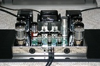
Picture of bias pots on Dynaco amp
They are very small pots mounted on a piece of blank PCB board and wired point to point. They are 50K and provide accurate and easy bias set.
Click on the picture and it should take you to a larger picture on Imageshack
- burnedfingers
- KT88
- Posts: 640
- Joined: Mon Sep 05, 2005 6:38 am
![]() by burnedfingers » Wed Dec 31, 2008 6:54 pm
by burnedfingers » Wed Dec 31, 2008 6:54 pm
http://img241.imageshack.us/my.php?image=3362eq2.pdf
Hopefully this will come up and shed some light on what I used.
I believe its a 1/2 watt control and its big enough to do the job.
Hopefully this will come up and shed some light on what I used.
I believe its a 1/2 watt control and its big enough to do the job.
- burnedfingers
- KT88
- Posts: 640
- Joined: Mon Sep 05, 2005 6:38 am
![]() by burnedfingers » Wed Dec 31, 2008 7:08 pm
by burnedfingers » Wed Dec 31, 2008 7:08 pm
For anyone wanting to take a closer look its Mouser PN 652-3362P-1-503LF
They are about .75 ea X 4
They are about .75 ea X 4
- burnedfingers
- KT88
- Posts: 640
- Joined: Mon Sep 05, 2005 6:38 am
Bias failure
![]() by FRE » Sun Jan 04, 2009 12:34 am
by FRE » Sun Jan 04, 2009 12:34 am
In case the bias fails when tubes have fixed bias, I wonder if it would be worthwhile to connect the cathodes via fuses.
- FRE
- Posts: 6
- Joined: Fri Jan 02, 2009 10:53 pm
- Location: Albuqerque NM
![]() by burnedfingers » Sun Jan 04, 2009 5:32 am
by burnedfingers » Sun Jan 04, 2009 5:32 am
In case the bias fails when tubes have fixed bias, I wonder if it would be worthwhile to connect the cathodes via fuses.
If that was the viable solution engineers would have done it years ago.
- burnedfingers
- KT88
- Posts: 640
- Joined: Mon Sep 05, 2005 6:38 am
![]() by EWBrown » Sun Jan 04, 2009 9:35 am
by EWBrown » Sun Jan 04, 2009 9:35 am
The "quick and dirty" way to "fuse" the EL34 cathodes, is to use 1/4 or 1/2 watt, 10 ohm resistors for each the (cathode current) measurement resistors.
Assuming 60 mA operation, that would result in 0.6V across teh resistors, so the actual power dissipated in then wiould be 0.6V X 0.06A, or 0.036 W (36 milliwatts). 50 mA would result in 25 mW, etc. So, 1/4 watt is more than sufficient for this purpose.
The resistors would act nicely as "fuses" should there be a serious bias problem or an internally shorted tube.
/ed B
Real Radios Glow in the Dark
-

EWBrown - Insulator & Iron Magnate
- Posts: 6389
- Joined: Wed Mar 19, 2003 6:03 am
- Location: Now located in Clay County, NC !
15 posts
• Page 1 of 1
Who is online
Users browsing this forum: No registered users and 5 guests