Edcor and Trafomatic Output Thread (was Meet my Amp...)

knowledge base for the classic Dynaco ST70

Edcor and Trafomatic Output Thread (was Meet my Amp...)

Postby SteveH » Sat Mar 01, 2008 1:23 pm

Gents,
So I finished wiring up my ST70 clone, grabbed some cheap speakers, and gave it a go. First started it up w/o rectification, and got -48v @ J6 and J21...Good ! So then I plug in my 5AR4's.......
Oscillation Yellow_Light_Colorz_PDT_21
I immediately shut down and look back over things. I have the 16 ohm lead from the output transformers wired directly into J12 and J13. I have a wire running from each of the NEG binding posts back to my star ground.
The amp uses Edcor 4.2k OPT's, and the Triode PA060S Power Transformers. I have wired in 2 5AR4's in parallel, and also added a UL/Triode mode switch (amp isn't happy in either setting)

I triple checked the wiring on the sockets:
Pin1 - Tied to Pin 8
Pin 2 - AC heat
Pin 3 - Plate lead from OPT
Pin 4 - Screen
Pin 5 - Grid Resistor
Pin 6 - Input from board, tied to Grid Resistor
Pin 7 - AC heat
Pin 8 - 10 ohm resistor to ground

On the board:
J22 - Rear right KT88
J23 - Front right KT88
J1 - rear left KT88
J2 - Front left KT88
J9 - To Star Ground
J4/J5 - Left AC heat
J15/J16 - Right AC heat
J6/J21 - Bias wipers
J7 - Left Input +
J8 - Left Input -
J17 - Right Input +
J10 Right Input -
J19/J20 - To SDS Board

When I checked Resistance on the PCB, the weird reading I got was like 990k ohm on Pins 2 of V2 and V3. Pin 2 of V1 read OK 475k ohms. Also on J1/J2/J22/J23 I wasn't getting the 1.2M value shown in the manual, but rather 127k for all four. Beyond that, everything else is by the book so to speak.

Maybe I hooked up the SDS board wrong ? I don't think so though...My connections are:

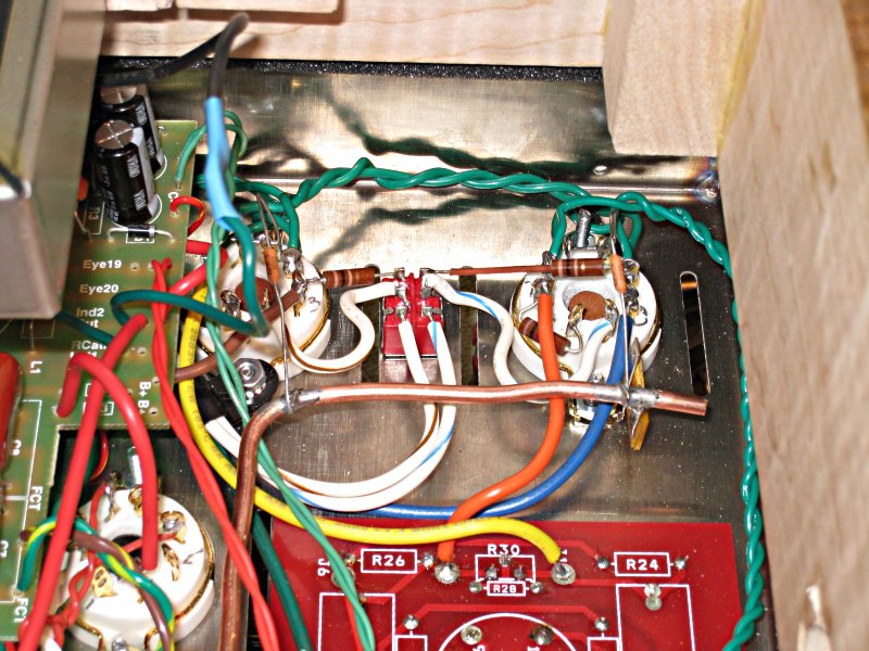
Pin 8 of the rectifier goes into the B+ trace of the board. Where it says "RCATH-Inductor" I have a line out going to two Hammond 159V's in series. The next "INDUCTOR 2 - OUT" I have the line coming in from the Hammonds, and the two B+ lines going to the OPT's. EYE 19 and EYE 20 go to the respective ports on the PCB

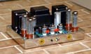
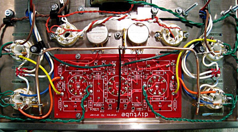
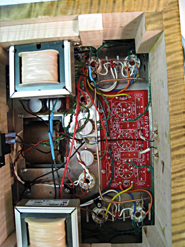
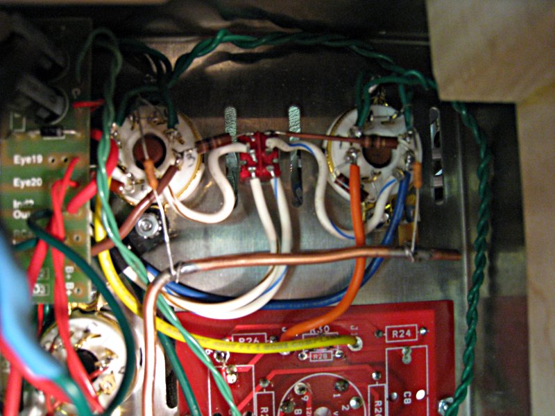
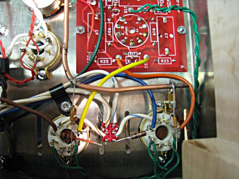
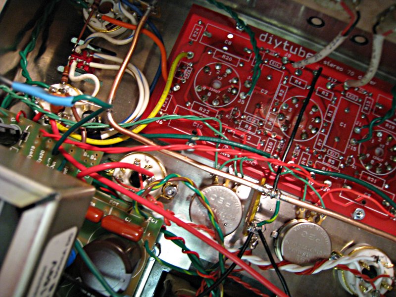
Here are some photos - I know it is hard; but if anything JUMPS out at you - please lemme know.

For Reference:
Image

Image

Image

Image

Image

Image

Image

Thanks for any help,
Steve

PS - I would like to be able to check voltages, etc - but I am afraid to while the amp isn't stable...
SteveH
KT88
 
Posts: 422
Joined: Thu Dec 14, 2006 5:38 pm
Location: Delaware

Postby mesherm » Sat Mar 01, 2008 1:37 pm

Disconnect the 16 ohm wires (negative feedback) at J12 J13. If the amp doesn't oscillate then power down, reconnect the 16 ohm wires and swap the yellow and orange wires on both channels going from the driver board to the EL3s.
Mike's N-1 Rule: When looking for N number of components to finish a job, you have a 95% chance of only finding N-1 of them.
User avatar
mesherm
KT88
 
Posts: 1232
Joined: Fri Aug 27, 2004 10:33 pm
Location: Alvin Texas

Postby SteveH » Sat Mar 01, 2008 4:50 pm

Thanks !
So I removed the 16 ohm lines from the NFB on the board and fired it up - no oscillations this time around - but serious 60 hz HUM. I'll swap the inputs and put the NFB line back to see if that solves the problem (but I don't think so).

Will report back shortly....
-Steve
SteveH
KT88
 
Posts: 422
Joined: Thu Dec 14, 2006 5:38 pm
Location: Delaware

Transformer issue ?

Postby Bob01605 » Sat Mar 01, 2008 5:22 pm

agree with mersherm - It's possible that those Edcor output transformers have the reverse phase of the standard Dynaco transformers and if you swap the ORANGE and YELLOW wires from the driver board to pin # 6 of the two output tubes on each channel - You might be OK.

I also like the way you squeezed those triode/pentode switches between the output tube pairs. The ST-70 in triode with a driver board upgrade (Diytube, Curcio or VTA) is a sweet sounding amp especially on acoustic jazz and vocals. The triode/pentode switches are easier to do on a VTA than the Diytube board because you don't use the original bias pots on the VTA board and can use those two 3/8" holes in the chassis for the triode/pentode switches.

Bob Latino
Bob Latino Custom Dynaco amplifiers

http://www.tubes4hifi.com/bob.htm
User avatar
Bob01605
 
Posts: 62
Joined: Fri Jun 09, 2006 5:32 pm
Location: New England, USA

Postby SteveH » Sat Mar 01, 2008 5:53 pm

Gents,
Ok - Well...I still have some hum through 102db speakers....BUT IT IS ALIVE ! I will have to mess with my grounding schema a bit more; but at least now I feel MUCH better. Please see my new thread for the 'right side up' shots Yellow_Light_Colorz_PDT_01

Thanks again,
Steve
SteveH
KT88
 
Posts: 422
Joined: Thu Dec 14, 2006 5:38 pm
Location: Delaware

Postby burnedfingers » Mon Mar 03, 2008 6:31 pm


The triode/pentode switches are easier to do on a VTA than the Diytube board because you don't use the original bias pots on the VTA board and can use those two 3/8" holes in the chassis for the triode/pentode switches.


Actually it is easier to get a quad pole double throw switch and use the original bias screw hole after drilling it larger to accomodate the switch and inserting a small black or chrome plug in the bias control holes. That is one nice thing about the VTA board having the controls in a usable area on the board. The only down side to the VTA board is that the bias controls operate backwards (counter clock wise to increase bias).
burnedfingers
KT88
 
Posts: 640
Joined: Mon Sep 05, 2005 6:38 am

Postby EWBrown » Tue Mar 04, 2008 6:51 am

The easiest method to correct the reversed phase is to simply swap the two connections (orange and yellow in your photos) from the driver board to the power tubes' G1 grids.

I have run into other reversed color coded leads on OPTs, so this isn't an unusual situation. Yellow_Light_Colorz_PDT_09

Then there are the Trafomatic OPTs with a color code unique to themselves. I had a 50/50 chance of getting it right on the first try, and of course, I had it wrong and ended up with a power oscillator :o Yellow_Light_Colorz_PDT_11

Update 3/7/08:

With the NFB loop disconnected, the overall amplifier gain will be significantly higher, and what should be a low-level hum can suddenly become much stronger with this extra 10-20 dB of overall gain.

/ed B in NH
Last edited by EWBrown on Fri Mar 07, 2008 7:15 am, edited 1 time in total.
Real Radios Glow in the Dark
User avatar
EWBrown
Insulator & Iron Magnate
 
Posts: 6389
Joined: Wed Mar 19, 2003 6:03 am
Location: Now located in Clay County, NC !

Postby Quad » Fri Mar 07, 2008 12:57 am

Ed, could you post the trafomatic toroid OPTs color codes?
I should be getting a set of them in a few weeks, and likely
to run into the same problem.
Quad
KT88
 
Posts: 254
Joined: Mon Jan 14, 2008 6:54 am
Location: India

Postby Shannon Parks » Fri Mar 07, 2008 7:06 am

Quad wrote:Ed, could you post the trafomatic toroid OPTs color codes?
I should be getting a set of them in a few weeks, and likely
to run into the same problem.


Whenever I build a feedback amp for the first time with a new type of output transformer I usually skip the phase calculations and wire it up but don't connect the feedback. Then I'll use some alligator clips to briefly connect it (almost a tap) while looking at a sine wave on a test load in my scope. Smaller means it's wired up correctly, larger (or super oscillation) means the secondary leads need swapped.
User avatar
Shannon Parks
Site Admin
 
Posts: 3764
Joined: Tue Mar 18, 2003 5:40 pm
Location: Poulsbo, Washington

Postby EWBrown » Fri Mar 07, 2008 7:12 am

I'll look them up and post them here next week- YMMV, as I'm not sure if their color code scheme remains standardized or constant...

They do supply a data / connection sheet with the trannies, but I still always do a DC Resistance check first... At least that makes ID'ing the primary connections a bit easier...

Are you getting the ST35 OPTs or the ST70 trannies (I have both types, and yes, they are different)...

/ed B in NH
Real Radios Glow in the Dark
User avatar
EWBrown
Insulator & Iron Magnate
 
Posts: 6389
Joined: Wed Mar 19, 2003 6:03 am
Location: Now located in Clay County, NC !

Postby Quad » Fri Mar 07, 2008 11:37 am

> Are you getting the ST35 OPTs or the ST70 trannies
> (I have both types, and yes, they are different)...

I am getting the ST70 OPTs and their toroid PT too.
A bit late to ask, since my order is already with Vista Audio,
but how does the amp sound with these?
Quad
KT88
 
Posts: 254
Joined: Mon Jan 14, 2008 6:54 am
Location: India

Postby EWBrown » Fri Mar 07, 2008 12:01 pm

I have the same thing only half-built so I cannot comment on its sound yet.

I'll bring in an OPT data sheet and post its information here.

Your power transformer is possibly different from mine, which has 2 separate 115VAC primaries, and the HV AC secondary has 360-325-0-325-360VAC (and a 55VAC bias tap) and two 6.3VAC and one 5.0 VAC filament windings.

/ed B in NH
Real Radios Glow in the Dark
User avatar
EWBrown
Insulator & Iron Magnate
 
Posts: 6389
Joined: Wed Mar 19, 2003 6:03 am
Location: Now located in Clay County, NC !

Trafomatic ST-70 OPT IDs

Postby EWBrown » Mon Mar 10, 2008 8:40 am

I have the Trafomatic ST-70, (50W, 4K3/4-8 ohm) data sheet here:

Primary Winding:

A1: Blue
40% G2-1: Black
B+ (Centre Tap): Red
40% G2-2 Black
A2: Orange

Note that the two SG taps are both black.
These should have small plastic clips with the lead IDs on them, if not, then a DC resistance check is needed to verify the correct tap for the corresponding anode.. I had the same situation with the Trafomatic ST35 OPTs.

Secondary:
0 (Zero or common / ground) : Yellow
4 ohms: White
8 ohms: Red

/ed B in NH
Real Radios Glow in the Dark
User avatar
EWBrown
Insulator & Iron Magnate
 
Posts: 6389
Joined: Wed Mar 19, 2003 6:03 am
Location: Now located in Clay County, NC !

Postby Quad » Wed Mar 12, 2008 6:34 am

Thanks, Ed!
Quad
KT88
 
Posts: 254
Joined: Mon Jan 14, 2008 6:54 am
Location: India

Trafomatic ST-70 PT IDs

Postby Quad » Mon Mar 31, 2008 11:04 pm

Hi Ed,

I got my Traformatic ST-70 set. The OPTs are fine, but
customs opened the power transformer (suspected land mine?).
It came sans any packing and the wiring dia is also missing.

I took a guess at the colors, but if you have the Trafomatic PT,
I'd appreciate if you could post the color code for the windings.

These are the windings -

4 orange wires labelled 1,2,3 and 4
2 windings - green pairs with white center tap.
Pair of Yellow wires
Pairs of red and blue, one grey tap, One yellow wire labelled "0"
A Yellow wire with green (or perhaps blue) stripes.

- Prasad
Quad
KT88
 
Posts: 254
Joined: Mon Jan 14, 2008 6:54 am
Location: India

Next

Return to st70

Who is online

Users browsing this forum: No registered users and 87 guests

cron