Hello...
Well, after following all the good advice
from you all, I gave 'er a shot and tried firing
it up.
Fireworks inside rectifyer tube. Yellow_Light_Colorz_PDT_21
Here's what happened and the procedure I used:
No variac (saving scarce funds in case I need new PA060)
so I built a dim bulb tester.
Put in a 3a FAST blow fuse (at the suggestion of our gracious host)
Started with no tubes and a 15w bulb, no prob,
shut off.....
Next, 40w bulb waiting several seconds between each..
Then 60w --> 100w.
So far so good..
Next, 7199s, followed same steps... still ok.
Then, added EL34s.... still good.
Next, 5AR4...
(always following the same steps)
15w bulb ok... for approx 1min.
40w bulb.... ok for maybe 2mins... then...
a soft pop and fireworks inside 5AR4.
Next, popped in 2nd 5AR4..
Forgot to put 15w bulb back in, so started with
40w.. (OOOPSie) Yellow_Light_Colorz_PDT_09
After about 2 mins, soft pop and fireworks.
(might have been 1 min.. I forget)
Backround info:
First 5AR4 is "International" branded, but
has "Made in Great Britan" etched in.
Always guessed its a 70s vintage Mullard, and
the shape looks like one, but...
if anyone says otherwise, I'll take your word for it.
2nd 5AR4 is older (ca. 1990 or so) Sovtek.
Neither had a lot of hrs on em, but they WERE
in 2 very old 70s with intermittent (the usual)
problems..
Amp is a total rebuild, except for irons and chassis...
PC3a replica (Vintage Electron) board,
Can cap is the 40-> 80-> 30-> 20 that others
here have used.
Btw... I had the inputs shorted the whole time
and spkrs connected to the OPTs.
Fuse did NOT blow either time!
The Last 5AR4 I have would be next, but I don't
want to risk it till I've heard from you guyz..
Till I have some sense of what might be causing
it, and having made every reasonable attempt
at fixing anything that might be wrong first.
HELP!! :-)
Sooooo frustrating to have come this far only
to get thwarted at the last step..
Thanx much in advance!!!
Greg
1st Startup Rectifyer Flashover... HELP! plz :-)
30 posts
• Page 1 of 2 • 1, 2
1st Startup Rectifyer Flashover... HELP! plz :-)
![]() by GrooveGrinder » Sun Feb 17, 2008 11:22 pm
by GrooveGrinder » Sun Feb 17, 2008 11:22 pm
- GrooveGrinder
- Posts: 40
- Joined: Thu Sep 27, 2007 11:05 pm
- Location: SoFla
![]() by kheper » Mon Feb 18, 2008 12:39 am
by kheper » Mon Feb 18, 2008 12:39 am
Rectifiers do not blow just for the heck of it.
The three possibilities I see are:
1. All of your rectifiers tubes were marginal
or dodgy. When they drew current, they
blew. If you used a known-to-be good
Mullard, this is unlikely.
2. A short, intermittent or otherwise, in the 'D'
or 'C' section of the multi-cap. You said that
you were using the '40-> 80-> 30-> 20' cap.
Are you positive that 40uf is the section
immediately after the rectifier? 80uf could
blow a rectifier.
Is the brand of your multi-cap , named 'CE'?
I know a tech who will no longer use them.
He says has experienced a %100 failure
rate. I have never had a failure with a
'CE' multi-cap.
3. A short somewhere 'downstream' on the
B+ rail. Check the insulation on the wiring.
-

kheper - KT88
- Posts: 1252
- Joined: Wed Dec 21, 2005 10:14 pm
- Location: Philly, PA
![]() by Shannon Parks » Mon Feb 18, 2008 6:46 am
by Shannon Parks » Mon Feb 18, 2008 6:46 am
Disclaimer: I admit I've never paid attention to the light bulb load test descriptions that are prevalent and very, very useful.
Isn't a 40W bulb a 360 ohm resistor? A 360 ohm resistor at 400V will draw >1A. This would blow any 5AR4.
Isn't a 40W bulb a 360 ohm resistor? A 360 ohm resistor at 400V will draw >1A. This would blow any 5AR4.
- designer of fine tube audio gear at (((parks audio)))
- founder and admin of the diytube forums
-

Shannon Parks - Site Admin
- Posts: 3764
- Joined: Tue Mar 18, 2003 5:40 pm
- Location: Poulsbo, Washington
Re: 1st Startup Rectifyer Flashover... HELP! plz :-)
![]() by dcriner » Mon Feb 18, 2008 10:02 am
by dcriner » Mon Feb 18, 2008 10:02 am
GrooveGrinder wrote:Amp is a total rebuild, except for irons and chassis...
PC3a replica (Vintage Electron) board,
Can cap is the 40-> 80-> 30-> 20 that others
here have used.
Greg
Greg, the original ST-70's filter cap was 30/20/20/20 (which is what I'm using in my ST-70).
I don't doubt that your upsized cap has been used successfully by others, but it puts extra strain on the 5AR4 recitifier, which is already working hard.
If you want to keep with your upsized cap, I would recommend a CL-90 inrush limiter and using a more rugged 5AR4 than Sovtek. I have had better luck with JJ.
Doug Criner
- dcriner
- KT88
- Posts: 309
- Joined: Mon Oct 23, 2006 4:19 pm
- Location: Illinois
![]() by mesherm » Mon Feb 18, 2008 10:37 am
by mesherm » Mon Feb 18, 2008 10:37 am
You didn't say what your bias voltage was set at. Pull all the tubes out and power up at full line voltage. Measure the voltage at pin 5 of the EL34 tube sockets and adjust the bias pots for the maximum negative voltage you have available. This should lower the current draw to almost nothing on startup. If the bias is set for too high a current draw on power up your rectifier will usually be the first to go before you notice the EL34 plates turning red.
Mike's N-1 Rule: When looking for N number of components to finish a job, you have a 95% chance of only finding N-1 of them.
-

mesherm - KT88
- Posts: 1232
- Joined: Fri Aug 27, 2004 10:33 pm
- Location: Alvin Texas
![]() by kheper » Mon Feb 18, 2008 11:33 am
by kheper » Mon Feb 18, 2008 11:33 am
dcriner wrote:
If he is using the cap below:
http://www.tubesandmore.com/scripts/fox ... 0-40-30-20
This will work fine, assuming that the cap is
in working condition and does not have the
80uf section immediately after the rectifier.
This cap is being made by CE, according
to the original Mallory specs. Lately, there
have been some reported failures of CE
multi-caps.
<b>GrooveGrinder</b>:
Make sure the section of the multi-cap
after the rectifier is <i>NOT</i> 80uf.
Following both mesherm's and separks's
advice.
1. Bias your output tubes at 50ma. per tube.
Your bias supply needs to be in working
order to begin. Pull the rectifier, give your
amp the FULL line voltage, then set the bias,
according to the manual.
2. If you are feeling daredevilish, turn off the
amp, put in a good rectifier and start the
amp at full line voltage.
DISCLAIMER: If there is a short in the B+
rail or your multi-cap is defective, the
rectifier will probably blow again after doing
'2'.
I don't doubt that your upsized cap has
been used successfully by others, but it puts
extra strain on the 5AR4 recitifier, which is
already working hard.
If he is using the cap below:
http://www.tubesandmore.com/scripts/fox ... 0-40-30-20
This will work fine, assuming that the cap is
in working condition and does not have the
80uf section immediately after the rectifier.
This cap is being made by CE, according
to the original Mallory specs. Lately, there
have been some reported failures of CE
multi-caps.
<b>GrooveGrinder</b>:
Make sure the section of the multi-cap
after the rectifier is <i>NOT</i> 80uf.
Following both mesherm's and separks's
advice.
1. Bias your output tubes at 50ma. per tube.
Your bias supply needs to be in working
order to begin. Pull the rectifier, give your
amp the FULL line voltage, then set the bias,
according to the manual.
2. If you are feeling daredevilish, turn off the
amp, put in a good rectifier and start the
amp at full line voltage.
DISCLAIMER: If there is a short in the B+
rail or your multi-cap is defective, the
rectifier will probably blow again after doing
'2'.
-
kheper - KT88
- Posts: 1252
- Joined: Wed Dec 21, 2005 10:14 pm
- Location: Philly, PA
![]() by Ty_Bower » Mon Feb 18, 2008 11:47 am
by Ty_Bower » Mon Feb 18, 2008 11:47 am
kheper wrote:The three possibilities I see are:
1. All of your rectifiers tubes were marginal...
2. A short in the multi-cap...
Are you positive that 40uf is the section immediately after the rectifier?
Is the brand of your multi-cap , named 'CE'?
3. A short somewhere 'downstream' on the B+ rail...
All good advice. I'm trying to keep in mind that he said it appears to be OK indefinitely as long as you don't plug in the EL34 output tubes. If the 5AR4 tubes were wonky, I might expect them to fail on initial powerup. If there were a short somewhere, why is OK without the output tubes?
I like the idea of setting the initial bias so the EL34 are idling at as low a current as possible. I'd be in favor of that. I'd also have a real careful look at the feedback coming from the output transformer. If that got reversed by accident, the amp would go into heavy oscillation. With the extra capacitance from the 40/80 cap up front, I might wager the output tubes could suck enough current to kill a 5AR4 after a short while.
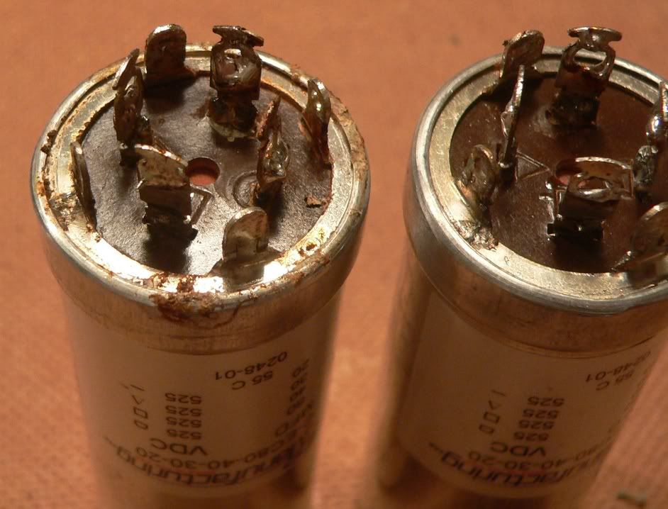
Edit... with all the comments about bad caps, I'll add this pic of what happened to a CE cap in a MkIII.
-

Ty_Bower - KT88
- Posts: 1494
- Joined: Wed Mar 21, 2007 2:50 pm
- Location: Newark, DE
![]() by kheper » Mon Feb 18, 2008 12:03 pm
by kheper » Mon Feb 18, 2008 12:03 pm
Ty_Bower wrote:
Because he put the rectifier in <i>AFTER</i>
he ran the amp with the EL-34s in place.
That is why I think he biased them correctly,
but he does not say this explicitly. Only when
there is some B+ on the amp does the
rectifier blow.
GrooveGrinder wrote:
If the 5AR4 tubes were wonky, I might expect
them to fail on initial powerup. If there were a
short somewhere, why is OK without the output tubes?
Because he put the rectifier in <i>AFTER</i>
he ran the amp with the EL-34s in place.
That is why I think he biased them correctly,
but he does not say this explicitly. Only when
there is some B+ on the amp does the
rectifier blow.
GrooveGrinder wrote:
Then, added EL34s.... still good.
Next, 5AR4...
[]
15w bulb ok... for approx 1min.
40w bulb.... ok for maybe 2mins... then...
a soft pop and fireworks inside 5AR4.
Next, popped in 2nd 5AR4
-
kheper - KT88
- Posts: 1252
- Joined: Wed Dec 21, 2005 10:14 pm
- Location: Philly, PA
![]() by mesherm » Mon Feb 18, 2008 1:27 pm
by mesherm » Mon Feb 18, 2008 1:27 pm
Other than just guessing at the cathode currents from measuring the bias voltage I don't see how you can properly set the bias WITHOUT a rectifier tube in place. The current changes as the tubes are loaded so at least for me its always been a back-and-forth adjustment until all the tubes are equal. Even if I am changing sets of tubes I always turn the bias voltage up so the absolute minimum current is flowing then after warmup slowly get all four bias currents set.
He stated that he had speakers connected so I'm betting he would have heard oscillation if the feedback were reversed.
He stated that he had speakers connected so I'm betting he would have heard oscillation if the feedback were reversed.
Mike's N-1 Rule: When looking for N number of components to finish a job, you have a 95% chance of only finding N-1 of them.
-
mesherm - KT88
- Posts: 1232
- Joined: Fri Aug 27, 2004 10:33 pm
- Location: Alvin Texas
![]() by GrooveGrinder » Mon Feb 18, 2008 1:39 pm
by GrooveGrinder » Mon Feb 18, 2008 1:39 pm
First off, I cannot thank all of you enough!
I could never get through this without your help.
Besides that, the education I'm getting is priceless!!
Next...
To clarify, everything seemed just fine with the
7199s and EL34s in!
Bear in mind though, that so far, its always been
connected to AC through the dim bulb tester and
the inputs shorted.
I was going to respond using quoting to several
statements in each post.. but I'll save time so as
to make this reply quick.
-----------------
Since I can't be certain the 2 5AR4s were very good,
I'll assume they were dodgy so we can move past
that.
I do believe, however, that the problem mainly
lies in a combination (possibly) of the other things
mentioned.
kheper:
I'll check the multicap C and D for shorts.
Yes, positive that 40uf is the section
immediately after the rectifier
..having double checked it at least 500 times
during/after assembly. LOL
I'll check it again.
The brand of your multi-cap may well be CE.
I've always suspected it is, though it was sourced
from Dynakitparts and has only their label.
I will re-check wire/insulation downstream..
This means between rectifier tube and multicap
only?
Shannon..
Why (if you don't mind explaining)is a "360 ohm resistor"
going to take out a rectifyer tube?
Not that I doubt... I just want to keep learning
and understanding.
Doug:
I didn't mean to imply that since others have used
it successfully that therefore it must be fine
:-)
ONLY to indicate the same configuration that has
been described here many times.
I actually have a CL-90...
Not "just on the bench".
Its actually installed in the amp.. the usual way..
(term on the transformer bolt)
Just NOT connected.. yet.
I'd reasoned that, given warnings I'd gotten about
excessive CL-90 heating with multiple/rapid
power on/off, that I'd best connect it after
all the dim-bulb startup tests.
Seems to have been a mistake.
I guess now's the time to connect it.
I'll order a JJ too.
mesherm:
I set the bias pots at center rotation, since I was
a bit confused as to what to do about it, and perhaps
overly anxious to move forward.
This has been a HUGE learning experience.
Would be an even better one, if its eventually
a sucessful one.. :-)
I will use the procedure you described on the
next try.
Just so I don't screw up some more...
"adjust the bias pots for the maximum negative voltage"
I should take to mean:
Adjust bias pots so the meter reads the highest voltage
available within their rotation?
Does the reading have to be taken at pin 5 of
the EL34 tube sockets, or is the usual place ok?
BTW... I heard nothing thru the spkrs.
No noise whatsoever, save for the very soft
pop when the rectifyer tubes flashed over.
And a very gentle/soft transformer grunt for
a sec as pwr was applied.
The latter, lessened each time pwr was applied
and was much less than was ever the case when
the amp was stock
(ie: not a problem)
More in a few... I just want to get this posted
ASAP.
G
- GrooveGrinder
- Posts: 40
- Joined: Thu Sep 27, 2007 11:05 pm
- Location: SoFla
![]() by kheper » Mon Feb 18, 2008 1:40 pm
by kheper » Mon Feb 18, 2008 1:40 pm
<b>mesherm wrote:</b>
Correct. My error.
I do not know what he has the bias pots set
at, so I should not have assumed anything.
Setting the bias voltages as negative as
possible <i>WITHOUT</i> the rectifier in
place is absolutely the first step.
Other than just guessing at the cathode
currents from measuring the bias voltage I
don't see how you can properly set the bias
WITHOUT a rectifier tube in place.
Correct. My error.
I do not know what he has the bias pots set
at, so I should not have assumed anything.
Setting the bias voltages as negative as
possible <i>WITHOUT</i> the rectifier in
place is absolutely the first step.
-
kheper - KT88
- Posts: 1252
- Joined: Wed Dec 21, 2005 10:14 pm
- Location: Philly, PA
![]() by GrooveGrinder » Mon Feb 18, 2008 1:53 pm
by GrooveGrinder » Mon Feb 18, 2008 1:53 pm
Ok...
Setting bias w/o rectifyer in place is essential.
I'm thinking of a procedure...
I won't make another move without advice. Yellow_Light_Colorz_PDT_02
1) make the above mentioned tests.
2) use a new JJ 5AR4
3) set bias BEFORE installing rectifyer tube..
4) connect CL-90
5) eliminate dim bulb thingy before doing 1)?
Am I forgetting anything?
Is this procedure sound?
I think the problem lays in the following:
Assuming a good cap, and good wiring (no shorts)
and a good 5AR4...
1) dim bulb acting as a resistor
2) upped multi-cap value with no CL90.
3) random (center-rotation) bias setting.
Maybe worse yet given the original PA060?
As always... I don't have words to sufficiently
communicate grattitude.
Gotta get back to work..
Will read replies and post again when I get home.
Greg
- GrooveGrinder
- Posts: 40
- Joined: Thu Sep 27, 2007 11:05 pm
- Location: SoFla
![]() by GrooveGrinder » Mon Feb 18, 2008 1:59 pm
by GrooveGrinder » Mon Feb 18, 2008 1:59 pm
A further thought..
Should I keep the inputs shorted and spkrs
connected?
Bear in mind, that so far the fast blow 3A didn't
blow.
Should I keep the inputs shorted and spkrs
connected?
Bear in mind, that so far the fast blow 3A didn't
blow.
- GrooveGrinder
- Posts: 40
- Joined: Thu Sep 27, 2007 11:05 pm
- Location: SoFla
![]() by erichayes » Mon Feb 18, 2008 2:34 pm
by erichayes » Mon Feb 18, 2008 2:34 pm
FWIW, "CE" is Campanella Electronics, which is the owner of CE Distributing and Antique Electronic Supply. They bought all of Mallory's "FP" tooling that was languishing down in Mexico after Mallory discontinued the FP line. They had to reverse-engineer and rebuild a lot of it, a process that took, IIRC, around two years. I bought some of their first run caps, and met with about a 50% failure rate. Since then (late '90s), I've had good luck, as long as I don't take them over 525V--even for a second. Same holds true for the 500V JJs, F-Ts and LCRs. They're all operating at their limits at those voltages, and doesn't take anything to push them over the edge.
To my knowledge, CE is the only manufacturer of high voltage FP (twist tab mount) style multi section electrolytic caps currently in production. If you find something else, like a CD or Sprague TVL, it's NOS and should be treated as such.
To my knowledge, CE is the only manufacturer of high voltage FP (twist tab mount) style multi section electrolytic caps currently in production. If you find something else, like a CD or Sprague TVL, it's NOS and should be treated as such.
Eric in the Jefferson State
- erichayes
- KT88
- Posts: 987
- Joined: Fri Jan 23, 2004 9:01 pm
- Location: McKinleyville CA
![]() by mesherm » Mon Feb 18, 2008 7:32 pm
by mesherm » Mon Feb 18, 2008 7:32 pm
You cant set the bias by measuring the normal test points unless the rectifier tube is in and all the EL34s are in so you must measure the voltage without the EL34s in at pin 5 either from the bottom or the top of the socket. The voltage at pin 5 should ALWAYS be negative with respect to ground. The more negative the voltage the less current the tube will conduct until eventually it will stop conducting altogether so to start with you want the pots set to give you the maximum negative voltage on pin 5.
Around -50 volts IIRC. Then when everything else checks out you can insert all the tubes and start slowly turning the bias pots to decrease the negative voltage. As you do that for one set of tubes it starts dropping the B+ which changes the tube bias so you do the adjustment by ping-ponging back from one set of tubes to the other measuring the bias at the normal bias test point back and forth. Eventually you will get both sets of tubes dialed in. You need to do this again whenever you change tubes. By that I mean turn the bias all the way negative. When I know I will be changing tube sets I turn the bias voltage up BEFORE I remove the old tubes. I have a feeling that the middle position you set the pots too was just enough to overload the rectifier tube after a few minutes but not enough to blow a fuse. As the rectifier and EL34s warmed the current went up and up until the rectifier flashed. If each EL34 pulled 70 or 80 ma it would probably have been enough to do in your rectifier. The power supply on a ST70 cannot supply a total 280 to 320 ma, way over a 5AR4s limit.
You will get some idea of what the total current was when you set your bias correctly and see how much rotation it takes on those pots.
It a shame you had to blow up that nice Mullard although maybe they are not quite dead yet.
BTW yes, keep inputs shorted and outputs loaded with either 8 ohm power resistors or speakers. If you didnt hear any noise I would say your feedback phasing is correct. I think your only error was in not maxing your negative bias first.
Mike's N-1 Rule: When looking for N number of components to finish a job, you have a 95% chance of only finding N-1 of them.
-
mesherm - KT88
- Posts: 1232
- Joined: Fri Aug 27, 2004 10:33 pm
- Location: Alvin Texas
30 posts
• Page 1 of 2 • 1, 2
Who is online
Users browsing this forum: No registered users and 78 guests