Hey everyone.
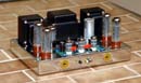
I'm perfoming a complicated (for me) upgrade of the PCB for my ST70. I'm using the VTA board and trying to follow the directions, but I'm getting confused with them:
1) The instructions that came with the VTA board say to connect the 2nd & 3rd section of the quad cap with a piece of wire and to replace the 22k resistor between the 1st & 2nd sections with a 2.2K resistor...
BUT:
2) the directions at the VTA installation page say:
"the 6.8K and 22K resistor on the quad cap can be removed and thrown away. The 2nd, 3rd, and 4th section of the quad cap can be connected together with a piece of wire. The choke will remain connected to the 1st and 2nd section of the quad cap." No mention of the 2.2K resistor.
HOWEVER:
3) the accompanying photos at the same website show a connection not between the 2nd & 3rd section of the quad cap, or even the 2nd, 3rd & 4th sections, but the 1st, 4th & 3rd sections. No mention of the 2.2K resistor here, either.
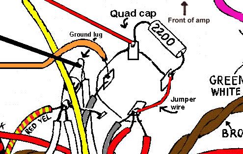
Here's a helpful pictoral from the same VTA site of the last quad cap wiring scheme I've mentioned, this time including a 2.2K resistor between the 3rd & 4th sections.
Can someone who's installed the VTA driver board help me out here?
Best,
Benjamin
VTA upgrade board
13 posts
• Page 1 of 1
VTA upgrade board
![]() by Brinkman » Tue Dec 04, 2007 7:55 pm
by Brinkman » Tue Dec 04, 2007 7:55 pm
- Brinkman
- Posts: 32
- Joined: Sat Jan 06, 2007 10:00 am
- Location: Portland, OR, North America
![]() by TomMcNally » Tue Dec 04, 2007 10:20 pm
by TomMcNally » Tue Dec 04, 2007 10:20 pm
Hi Benjamin -
I don't have any personal experience with the boards,
but having looked it all over, I'd go with the photographs
and ignore the text and pictorial.
You're basically just paralleling the capacitor sections
for a higher total value.
... tom
I don't have any personal experience with the boards,
but having looked it all over, I'd go with the photographs
and ignore the text and pictorial.
You're basically just paralleling the capacitor sections
for a higher total value.
... tom
-

TomMcNally - Darling du Jour
- Posts: 2729
- Joined: Sat Nov 19, 2005 2:19 pm
- Location: Northfield, NJ
![]() by Brinkman » Tue Dec 04, 2007 11:10 pm
by Brinkman » Tue Dec 04, 2007 11:10 pm
TomMcNally wrote:Hi Benjamin -
I don't have any personal experience with the boards,
but having looked it all over, I'd go with the photographs
and ignore the text and pictorial.
You're basically just paralleling the capacitor sections
for a higher total value.
... tom
I have no idea how old the photos are and if my board is a revision of it. Basically, what I'm trying to do is find out how the hell the VTA board wants the quad cap to be reconfigured so I can make sure the wiring of my SDS cap board mirrors it.
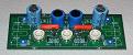
I already modified the ST70 with the SDS cap upgrade, so I am no longer using the quad cap, but to install the new VTA driver board, I'm going to need my can cap replacement to be wired in a similar fashion.
I'm probably over-thinking this.
Best,
Benjamin
- Brinkman
- Posts: 32
- Joined: Sat Jan 06, 2007 10:00 am
- Location: Portland, OR, North America
![]() by mesherm » Wed Dec 05, 2007 12:32 am
by mesherm » Wed Dec 05, 2007 12:32 am
Remove both resistors and replace them with pieces of solid wire or just solder a wire across each resistor. This connects the 2nd 3rd and 4th sections together so you have essentially two filter caps. The VA and PI have their own filter networks on the VTA board so you don't need the 3rd and 4th filter section. By connecting them to the 2nd section you increase the capacitance at the B+ feed to the power tubes where it does the most good. You could just leave the 3rd and 4th unconnected but why waste good usefull capacitance. The wires from the 3rd and 4th sections of the SDS that went to the original driver board can be removed. You will also need to unsolder the bias tap wire from the SDS board and reconnect it on the VTA board. You can remove all the bias wires from the two bias pots as they are not used. The 4 bias trimpots on the VTA board will be used instead. You will need to add an extra two bias check tap points also and add a 10 ohm cathode resistor at each EL34 socket for a total of 4.
I have used the VTA driver in 4 amps so far and have been quite pleased.
If you have any other wiring questions just email me directly.
I have used the VTA driver in 4 amps so far and have been quite pleased.
If you have any other wiring questions just email me directly.
Mike's N-1 Rule: When looking for N number of components to finish a job, you have a 95% chance of only finding N-1 of them.
-

mesherm - KT88
- Posts: 1232
- Joined: Fri Aug 27, 2004 10:33 pm
- Location: Alvin Texas
![]() by Brinkman » Wed Dec 05, 2007 11:53 am
by Brinkman » Wed Dec 05, 2007 11:53 am
Excellent! Thanks for clearing up the quad cap issue. I am also pleased my own conclusions regarding the disconnection of the bias portion of the SDS board were echoed in your post. Am feeling confident.
If all goes well today, my updated Forte crossovers will arrive, my new driver board will be installed, and I'll have a backlog of tubes to roll for the driver board (NOS trios of 12bh7s, 12ax7s, & 12au7s & a trio of JJ ECC82s) and the output tubes, some Winged =C= EL34s.
Will email you with a negative feedback question.
Best,
Benjamin
- Brinkman
- Posts: 32
- Joined: Sat Jan 06, 2007 10:00 am
- Location: Portland, OR, North America
Re: Correct VTA quad cap hookup
![]() by Bob01605 » Thu Dec 06, 2007 4:32 pm
by Bob01605 » Thu Dec 06, 2007 4:32 pm
mesherm wrote:Remove both resistors and replace them with pieces of solid wire or just solder a wire across each resistor. This connects the 2nd 3rd and 4th sections together so you have essentially two filter caps. The VA and PI have their own filter networks on the VTA board so you don't need the 3rd and 4th filter section. By connecting them to the 2nd section you increase the capacitance at the B+ feed to the power tubes where it does the most good. You could just leave the 3rd and 4th unconnected but why waste good usefull capacitance. The wires from the 3rd and 4th sections of the SDS that went to the original driver board can be removed. You will also need to unsolder the bias tap wire from the SDS board and reconnect it on the VTA board. You can remove all the bias wires from the two bias pots as they are not used. The 4 bias trimpots on the VTA board will be used instead. You will need to add an extra two bias check tap points also and add a 10 ohm cathode resistor at each EL34 socket for a total of 4.
I have used the VTA driver in 4 amps so far and have been quite pleased.
If you have any other wiring questions just email me directly.
Although what you say above will work > this is not exactly what Roy Mottram had in mind for his board regardless of what his instructions say. I have Emailed him directly and below is what he recommends.
Section 1 of the quad cap - TWO connections
1. A wire to pin 8 of the rectifier tube
2. One of the choke leads
Section 2 of the quad cap (that faces the back of the amp) - FOUR connections
1. The second choke lead
2. Red wire from LEFT output transformer
3. Red wire from RIGHT output transformer
4. One end of a jumper
Section 3 of the quad cap - TWO connections
1. The OTHER end of the jumper wire
2. One end of the 2.2 K ohm 1 watt resistor
Section 4 of the quad cap - TWO connections
1. The OTHER end of the 2.2 K ohm 1 watt resistor
2. One end of a wire that brings the B+ to the driver board
The reason for the jumper is to tie together sections 2 and 3 and add the capacitance of both sections together. On a STOCK quad cap 20 + 20 = 40 Mfd. The reason for the 2.2K resistor is to drop the B+ by 20 volts to about 420-440 volts which is the voltage that Roy Mottram has specified as the correct operating B+ for his board. Check link to photo below ..
http://i9.photobucket.com/albums/a78/Bo ... psetup.jpg
Bob Latino
-
Bob01605 - Posts: 62
- Joined: Fri Jun 09, 2006 5:32 pm
- Location: New England, USA
![]() by mesherm » Thu Dec 06, 2007 7:03 pm
by mesherm » Thu Dec 06, 2007 7:03 pm
The reason for the 2.2K resistor is to drop the B+ by 20 volts to about 420-440 volts which is the voltage that Roy Mottram has specified as the correct operating B+ for his board.
The voltage after the choke on a stock ST70 with all four EL34s running at 40-50 ma each should not be over 440 volts unless the PT has been replaced or the rectifier tube replaced with diodes. Solder a 2.4k 1w resistor and a bare wire in parallel with the 22k and check the voltage at normal operation. If it is too high then just snip the bare wire out and the 22k+2.4k combo wll give a nominal 2.2k.
Mike's N-1 Rule: When looking for N number of components to finish a job, you have a 95% chance of only finding N-1 of them.
-
mesherm - KT88
- Posts: 1232
- Joined: Fri Aug 27, 2004 10:33 pm
- Location: Alvin Texas
![]() by Brinkman » Thu Dec 06, 2007 8:43 pm
by Brinkman » Thu Dec 06, 2007 8:43 pm
With all due respect, Roy Mottram's instructions are incorrect; insofar as he has mislabelled the quad cap sections.
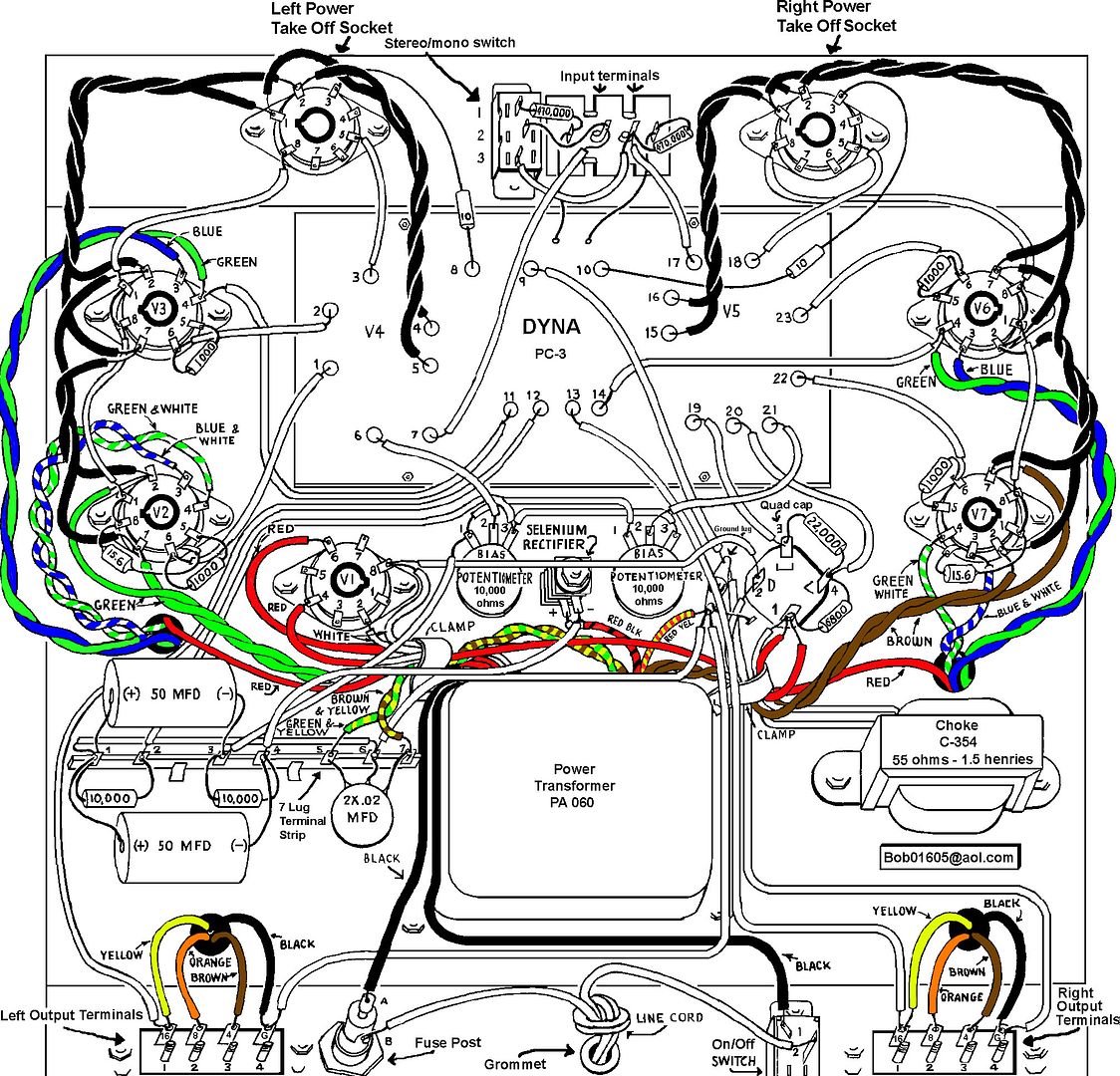
I have found a high-resolution scan of the ST-70 wiring pictorial. This image is courtesy of Bob Latino from an Audio Asylum thread. This is the exact same pictorial that I used to construct my recent-production ST-70 kit (albeit with color & a selenium rectifier), and I assume it is consistent with the original-production ST-70 kit wiring pictorial.
Look at the quad cap. Clockwise, 6 o'clock, 9 o'clock, 12 o'clock & 3 o'clock are labelled Sections 1,2,3 & 4 respectively. I was able to install my SDS cap board with this as a reference (without screwing up), so I assume this labelling is historically correct.
Perhaps there's other ST-70s with a wiring pictorial that is different. If this is the case, than I imagine that one of these may have been Roy Mottram's reference and thus the source of the discrepancy between the VTA driver board instructions and my point of reference, which is the above linked wiring pictorial.
I will email Kevin at Dynakit (whom I purchased my kit from) to see if he can verify the authenticity of the pictorial he is supplying.
Perhaps the section designation of the quad cap is somewhat arbitrary and can be wired several ways. I wouldn't know. What I do know, however, is that the integrity of the ST-70 as a teaching tool is compromised when basic labelling of components are not consistent. Accuracy is everything, especially with potentially lethal voltages present.
FWIW, with respect to the wiring pictorial I am familiar with, the corresponding cap sections on the SDS cap board are, from left to right, 3, 4, 1 & 2.
Hopefully this can explain why I was so confused at the start of this thread.
Everyone's input has been integral to sorting out this mess, please add more!
Best,
Benjamin
- Brinkman
- Posts: 32
- Joined: Sat Jan 06, 2007 10:00 am
- Location: Portland, OR, North America
Stock Dynaco and VTA quad cap connections
![]() by Bob01605 » Sat Dec 08, 2007 7:19 am
by Bob01605 » Sat Dec 08, 2007 7:19 am
Much of the confusion about the quad cap connections are because Dynaco (stupidly) marked them in a way that IMHO leads to confusion. Dynaco marked them starting with "1" in the six o'clock position and then went around clockwise - BUT - the ACTUAL FIRST section of the quad cap is the section that receives current from the rectifier tube and that is section "2" on the Dynaco pictorial. Dynaco went around clockwise with their numbering but the current flow is in the opposite direction - COUNTERCLOCKWISE
The "FIRST" section is the one at 9 o'clock that receives power from pin 8 of the rectifier tube
The "SECOND" section is at 6 o'clock
The "THIRD" section is at 3 o'clock
The "FOURTH" section is at 12 o'clock
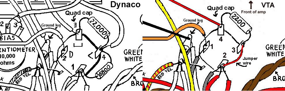
Check the link below which shows a comparison between the two numbering systems
http://i9.photobucket.com/albums/a78/Bo ... rences.jpg
Bob Latino
The "FIRST" section is the one at 9 o'clock that receives power from pin 8 of the rectifier tube
The "SECOND" section is at 6 o'clock
The "THIRD" section is at 3 o'clock
The "FOURTH" section is at 12 o'clock
Check the link below which shows a comparison between the two numbering systems
http://i9.photobucket.com/albums/a78/Bo ... rences.jpg
Bob Latino
-
Bob01605 - Posts: 62
- Joined: Fri Jun 09, 2006 5:32 pm
- Location: New England, USA
quad caps and VTA mod
![]() by tubes4hifi » Tue Jan 01, 2008 12:24 am
by tubes4hifi » Tue Jan 01, 2008 12:24 am
yes, Bob is correct on this
also, note the problem originates with the fact that the ORIGINAL quad cap and the new replacement UPGRADED quad cap are oriented differently.
I'm always amazed that when customers have a question they ask everyone else first instead of asking the source.
Also I must apologize that some of the photos and instructions on my website are 3-4 years old, I've been selling this mod for 20 years now, and there have been a few variations!
Roy www.tubes4hifi.com/st70.htm
-
tubes4hifi - Posts: 113
- Joined: Thu Jan 15, 2004 12:52 pm
- Location: Tacoma, WA
Re: quad caps and VTA mod
![]() by Brinkman » Thu Jan 03, 2008 8:24 pm
by Brinkman » Thu Jan 03, 2008 8:24 pm
tubes4hifi wrote:I'm always amazed that when customers have a question they ask everyone else first instead of asking the source.
It's not that amazing, really. I just didn't expect you to be familiar with the SDS cap board which I was already using in lieu of the can capacitor your installation instructions assume is in place.
I'm sure you'd agree message boards such as these, which draw from the collective experience of a multitude of folks, are a lot more useful a place to troubleshoot problems such as mine, as opposed to a private back-and-forth on my behalf between both you and Triode Electronics.
I'll post a photo soon, detailing how to install your VTA board with the SDS board in place as well. Both modifications are highly recommended, and I look forward to trying out a DIYtube driver board in the near future. Perhaps on a pair of Mk. IIIs...
- Brinkman
- Posts: 32
- Joined: Sat Jan 06, 2007 10:00 am
- Location: Portland, OR, North America
![]() by mesherm » Fri Jan 04, 2008 4:29 pm
by mesherm » Fri Jan 04, 2008 4:29 pm
What are the circuit differences between the VTA board and Shannon’s DIY Tube board?
Shannon's is made to pretty much drop into an ST70 power supply wise. His PI stage uses a long tail pair with a constant current source, LM234, as the phase inverter tail. He uses the stock ST70 bias pots and a trim pot on board for each pair of output tubes to balance the idle currents of the output tubes. Shannon's uses a 12AU7 type for VA and a 12BH7 type for PI duty
Roy's VTA has its own on board VA and PI power supply network and only needs voltage from the output tube supply. His PI is a Schimdt type long tail pair and has a trim pot per side to precisely match the phase inverters output. There is a trimpot onboard for each output tube so only raw AC bias voltage is needed. Roy's uses three 12AT7 types for both VA and PI duty.
If I were to upgrade an ST70 I would probably use (and have used) Shannon's but if rolling my own ST70 clone I would probably use (and have used) Roy's board.
Either one is an improvement over the stock circuit.
Mike's N-1 Rule: When looking for N number of components to finish a job, you have a 95% chance of only finding N-1 of them.
-
mesherm - KT88
- Posts: 1232
- Joined: Fri Aug 27, 2004 10:33 pm
- Location: Alvin Texas
13 posts
• Page 1 of 1
Who is online
Users browsing this forum: No registered users and 90 guests