reading 0 V on pins 1 and 8
26 posts
• Page 1 of 2 • 1, 2
reading 0 V on pins 1 and 8
![]() by guitarpsych » Thu Mar 29, 2007 8:38 pm
by guitarpsych » Thu Mar 29, 2007 8:38 pm
I'm getting a 0 reading on pins 1 and 8 of the power tubes on one side. Does that mean the transformer is blown, or could it be something... less expensive?
- guitarpsych
- Posts: 44
- Joined: Sat Oct 21, 2006 12:12 pm
![]() by TomMcNally » Thu Mar 29, 2007 9:01 pm
by TomMcNally » Thu Mar 29, 2007 9:01 pm
Pis 1 and 8 of each EL-34 are connected together, then to the other tube, then to ground through the 15.6 ohm resistor ... are you sure the reisitor is good ? If it's open, the channel won't work.
-

TomMcNally - Darling du Jour
- Posts: 2729
- Joined: Sat Nov 19, 2005 2:19 pm
- Location: Northfield, NJ
![]() by guitarpsych » Thu Mar 29, 2007 9:52 pm
by guitarpsych » Thu Mar 29, 2007 9:52 pm
I just put in a new one just in case and it didn't change anything.
- guitarpsych
- Posts: 44
- Joined: Sat Oct 21, 2006 12:12 pm
![]() by EWBrown » Fri Mar 30, 2007 5:29 am
by EWBrown » Fri Mar 30, 2007 5:29 am
Seeing your other posting with the voltage checks, it looks like B+ is getting through the OPT primary to the plates and SGs, but for some reason the tubes are not drawing any current.
Possibilities: The EL34s are totally dead (I've rarely seen a bad tube that didn't have some emission, unless the filament was burned out.). Bad socket contacts, or the G1 bias voltage is set too negative. (is -33.3V a normal level?)
When I'm building up a new amp, or fixing an old one, I'll do the initial power tubes' bias setting, with just the rectifier tube and power tubes (EL34s in this case) in place, and adjust the bias as required. After that looks good, I'll insert the remaining river tubes, check again, and then let it burn in a while, then re-check and adjust bias as neded.
/ed B in NH (still waking up and fignhting a cranky computer)
Real Radios Glow in the Dark
-

EWBrown - Insulator & Iron Magnate
- Posts: 6389
- Joined: Wed Mar 19, 2003 6:03 am
- Location: Now located in Clay County, NC !
![]() by guitarpsych » Sat Mar 31, 2007 12:00 am
by guitarpsych » Sat Mar 31, 2007 12:00 am
Thanks for you ideas.
The bias reads 0 wherever I have the bias adjustment.
I've tried swapping the left channel tubes with the right channel tubes andit doesn't help (one side works, the other does not, the problem doesn't move with the tubes).
The sockets look good. I went through with a meter touching from from front to back and 0 resistance on each pin.
Can you think of anything else it might be? This is driving me crazy. I can't figure out what it could be.
- guitarpsych
- Posts: 44
- Joined: Sat Oct 21, 2006 12:12 pm
![]() by guitarpsych » Sat Mar 31, 2007 8:29 am
by guitarpsych » Sat Mar 31, 2007 8:29 am
It jumps around when measuring the can metal case. The cap can metal cover does not look directly attached to anything but does sit very close to the chassis (though not soldered to it). There is a pin on the bottom (in addition to the 4 capacitor pins) that goes to ground, and from that to pin 1 or 8 of the power tube, it reads 10.2 ohms. I had done what someone suggested and put new 10 ohm resistors in place of the old white resistor. I believe that's why it's reading 10 ohms instead of 15.
- guitarpsych
- Posts: 44
- Joined: Sat Oct 21, 2006 12:12 pm
![]() by mesherm » Sat Mar 31, 2007 12:03 pm
by mesherm » Sat Mar 31, 2007 12:03 pm
OK, so that side is getting B+ to the plates and screen grids through the OT.
The cathodes seem to be grounded through the 10 ohm resistors.
The B+ voltages seem about right considering one side isn't drawing current.
I assume the EL34 heaters are lighting up (they had voltage applied).
The bias voltage of around -33 volts seems ballparkish.
If it wasn't getting signal the tubes would still draw idle current yet there is no voltage across the 10 ohm resistor of 0.8 to 1 volt.
When you swap tube pairs from one side to the other the bad side stays bad.
Ok, I'm at a loss. Any way to snap a high res pic of the underside wiring and post it?
-

mesherm - KT88
- Posts: 1232
- Joined: Fri Aug 27, 2004 10:33 pm
- Location: Alvin Texas
![]() by guitarpsych » Sat Mar 31, 2007 12:54 pm
by guitarpsych » Sat Mar 31, 2007 12:54 pm
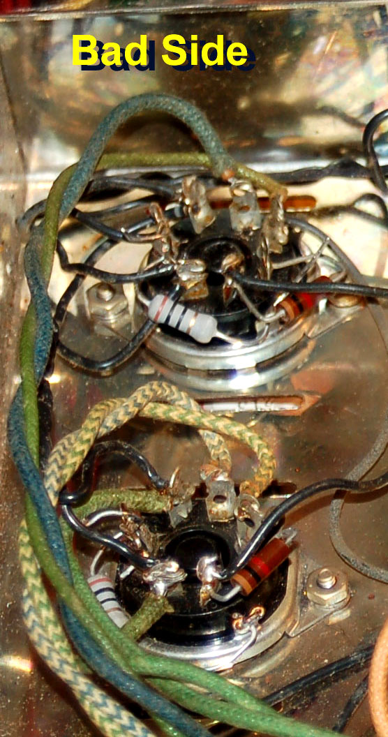
Here is a shot:
I'm posting a closeup of the bad side power tube sockets and giving links to the larger image entire amp so everyone doesn't have to download the image if they don't want to. Just a reminder... this problem was happenig even before I put the new 10ohm resistors in.
Best image:
http://www.astoundingtrousers.com/images/st70-2.jpg
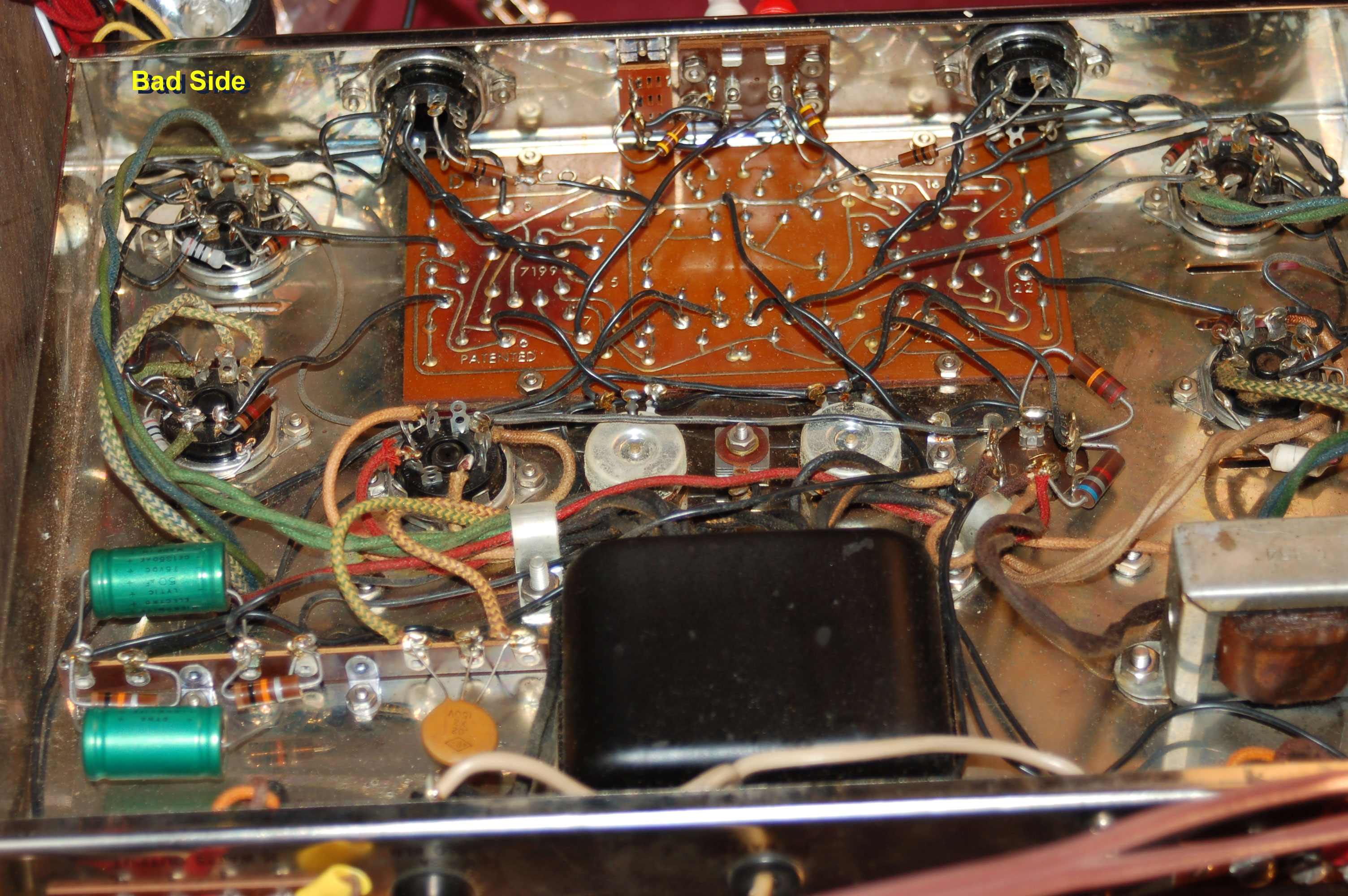
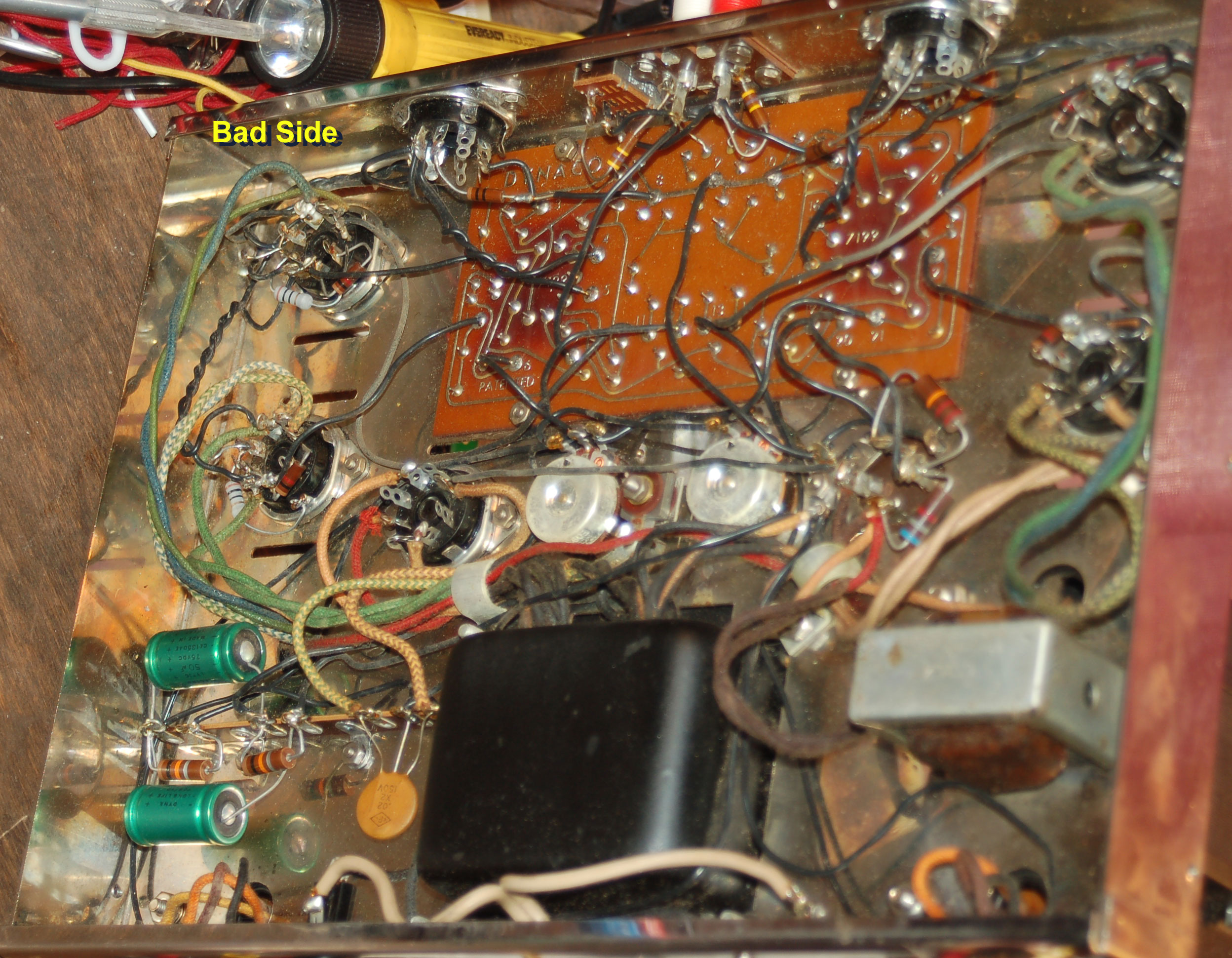
A couple of others at slightly different angles:
http://www.astoundingtrousers.com/images/st70-1.jpg
http://www.astoundingtrousers.com/images/st70-3.jpg
I'm posting a closeup of the bad side power tube sockets and giving links to the larger image entire amp so everyone doesn't have to download the image if they don't want to. Just a reminder... this problem was happenig even before I put the new 10ohm resistors in.
Best image:
http://www.astoundingtrousers.com/images/st70-2.jpg
A couple of others at slightly different angles:
http://www.astoundingtrousers.com/images/st70-1.jpg
http://www.astoundingtrousers.com/images/st70-3.jpg
- guitarpsych
- Posts: 44
- Joined: Sat Oct 21, 2006 12:12 pm
![]() by TomMcNally » Sat Mar 31, 2007 12:54 pm
by TomMcNally » Sat Mar 31, 2007 12:54 pm
On the bad side, what does "ground" the 10 ohm resistor solder to ? If it's the tube socket, I'm thinking it's not grounded well.
-
TomMcNally - Darling du Jour
- Posts: 2729
- Joined: Sat Nov 19, 2005 2:19 pm
- Location: Northfield, NJ
![]() by TomMcNally » Sat Mar 31, 2007 1:02 pm
by TomMcNally » Sat Mar 31, 2007 1:02 pm
You posted the pics while I was typing that last reply ! What's the long tail on the 10 ohm resistor ? It might be touching something. Again, I think that ground on the tube socket is no good, due to corrosion, etc ... try a jumper wire to a better ground and see if the amp works.
-
TomMcNally - Darling du Jour
- Posts: 2729
- Joined: Sat Nov 19, 2005 2:19 pm
- Location: Northfield, NJ
![]() by guitarpsych » Sat Mar 31, 2007 1:07 pm
by guitarpsych » Sat Mar 31, 2007 1:07 pm
The long tail is just because I hadn't clipped it yet.. probably should (but the problem was happening before I put this resistor in).
It is grounded to a lug that comes off the piece of metal holding the socket in place. I have tried measuring from pin 1 of the bad power tube side and put the other end of the meter at various places on the chassis and it reads correct, 10.2 ohms. I guess I can try soldering it somewhere else.
It is grounded to a lug that comes off the piece of metal holding the socket in place. I have tried measuring from pin 1 of the bad power tube side and put the other end of the meter at various places on the chassis and it reads correct, 10.2 ohms. I guess I can try soldering it somewhere else.
- guitarpsych
- Posts: 44
- Joined: Sat Oct 21, 2006 12:12 pm
![]() by TomMcNally » Sat Mar 31, 2007 1:14 pm
by TomMcNally » Sat Mar 31, 2007 1:14 pm
OK - forget that idea if you've checked the ground. I'm wondering if you have some dirty tube socket pins. You might want to remove the tubes and tighten the pins with a tiny screwdriver (make sure you discharge the caps first) One of the first thing we all do when we rebuild those amps is replace the tube sockets. Make sure the tube pins are clean too.
-
TomMcNally - Darling du Jour
- Posts: 2729
- Joined: Sat Nov 19, 2005 2:19 pm
- Location: Northfield, NJ
![]() by guitarpsych » Sat Mar 31, 2007 1:29 pm
by guitarpsych » Sat Mar 31, 2007 1:29 pm
I did that (tightened the pins the tubes insert into).
I am wondering, if you read resistance from pin 2 to pin 7, should it be 0?
I am wondering, if you read resistance from pin 2 to pin 7, should it be 0?
- guitarpsych
- Posts: 44
- Joined: Sat Oct 21, 2006 12:12 pm
![]() by TomMcNally » Sat Mar 31, 2007 1:37 pm
by TomMcNally » Sat Mar 31, 2007 1:37 pm
Pins 2 and 7 are the EL-34's filament, it should be a low resistance.
Are the tubes lighting up ?
Are the tubes lighting up ?
-
TomMcNally - Darling du Jour
- Posts: 2729
- Joined: Sat Nov 19, 2005 2:19 pm
- Location: Northfield, NJ
26 posts
• Page 1 of 2 • 1, 2
Who is online
Users browsing this forum: No registered users and 100 guests