Tonight I replaced my selenium rectifier (was pretty much open) with a 1N4004 diode. I left the old 50uf capacitors in place as I checked them for leakage and capacitance, they were good. I now have a much greater range on the bias potentiometers and now the pot is about 1/3 of the way instead of 1 side. I am pretty much done with my restoration. I am real happy with the ST-70. Now if I can find a few ST-70's at a garage sale....
Regards,
Sal Brisindi
Bias selenium rectifier replaced with a 1N4004 diode
11 posts
• Page 1 of 1
Bias selenium rectifier replaced with a 1N4004 diode
![]() by Sal Brisindi » Tue Mar 27, 2007 8:40 pm
by Sal Brisindi » Tue Mar 27, 2007 8:40 pm
-
Sal Brisindi - KT88
- Posts: 374
- Joined: Thu Mar 22, 2007 5:21 am
- Location: Freehold N.J.
![]() by wiredbecker » Wed Mar 28, 2007 1:08 am
by wiredbecker » Wed Mar 28, 2007 1:08 am
Congrats Sal. As you complete your ST70 restoration saga, I begin mine!
-

wiredbecker - KT88
- Posts: 301
- Joined: Mon Mar 26, 2007 3:48 pm
- Location: Albany Landfill, CA
![]() by wiredbecker » Thu Mar 29, 2007 8:33 pm
by wiredbecker » Thu Mar 29, 2007 8:33 pm
Hey Sal,
when I search for "how to set dynaco 70 tube bias" on google, your ST70 page appears as about the 5th result. My amp has a slight hum too. I was hoping, probably naively, that the hum was the result of an unset bias and not a buncha old caps that need replacing. I SHOULD BE SO LUCKY.
The reality is that I should probably just replace them all anway
-
wiredbecker - KT88
- Posts: 301
- Joined: Mon Mar 26, 2007 3:48 pm
- Location: Albany Landfill, CA
![]() by Sal Brisindi » Sat Mar 31, 2007 6:58 pm
by Sal Brisindi » Sat Mar 31, 2007 6:58 pm
At minimum you should replace the quad electrolytic capacitor, a little pricey at $40.00 with shipping but I chose to go that route to keep the ST-70 "original" looking vs. a set of caps underneath. Next I would replace the 6 capacitors (4 -.1uf and 2 -.05uf) on the printed circuit board being very careful as the copper trace easily will lift from the board. Do not over heat the copper trace. The next step is to replace the bias selenium rectifier with a 1N4004 or better diode. My 50uf bias caps were good, no leakage and the capacitance were within specs so I left them alone.
Have fun!
Sal Brisindi
Have fun!
Sal Brisindi
-
Sal Brisindi - KT88
- Posts: 374
- Joined: Thu Mar 22, 2007 5:21 am
- Location: Freehold N.J.
![]() by wiredbecker » Sun Apr 01, 2007 1:19 am
by wiredbecker » Sun Apr 01, 2007 1:19 am
Thanks for the advice. I went ahead and picked up the SDS cap board from Triode, but broke my wrist soon after. No soldering fun for me for a while unless I get really good at working with my left hand. Yellow_Light_Colorz_PDT_07 I decided that the amp would still appear stock while hiding the board underneath. The empty quad can continue to live on top, albeit empty.
What is the sound of one hand typing? Yellow_Light_Colorz_PDT_09 I need to go to bed or something.
So regarding bias rectifier replacement, I know the sds board provides a provision for it.. I'm just not sure how you did it. Where did the 1N4004 go? You aren't talking about removing your rectifier tube are you? I'm so confused.
-
wiredbecker - KT88
- Posts: 301
- Joined: Mon Mar 26, 2007 3:48 pm
- Location: Albany Landfill, CA
![]() by Sal Brisindi » Sun Apr 01, 2007 8:17 am
by Sal Brisindi » Sun Apr 01, 2007 8:17 am
Sorry to hear about your wrist, you can go to Radio Shack and buy a left handed soldering iron.. Yellow_Light_Colorz_PDT_09
The bias selenium rectifier has nothing to do with the rectifer tube. If you look at a schematic of the ST-70 you will see a tap on the high voltage winding going to a diode, a couple of 10K resistors, 2 50uf capacitors and 2 5K potentiometers.
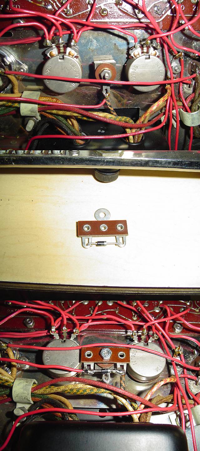
About the bias selenium rectifier and how I replaced it, attached is a photo. In the top photo you will see the bias selenium rectifier in between the 2 bias potentiometers before I replaced it.
In the second photo you will see I soldered a 1N4004 diode on a terminal strip. What I did was drill out the middle mounting post from the terminal strip and used that hole to mount the diode assembly to the same screw that held the original selenium rectifier which I left in place and removed the wires to it.
In the bottom photo you will see the diode screwed in with the old selenium rectifier and wires attached to the diode assembly.
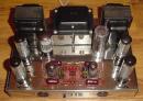
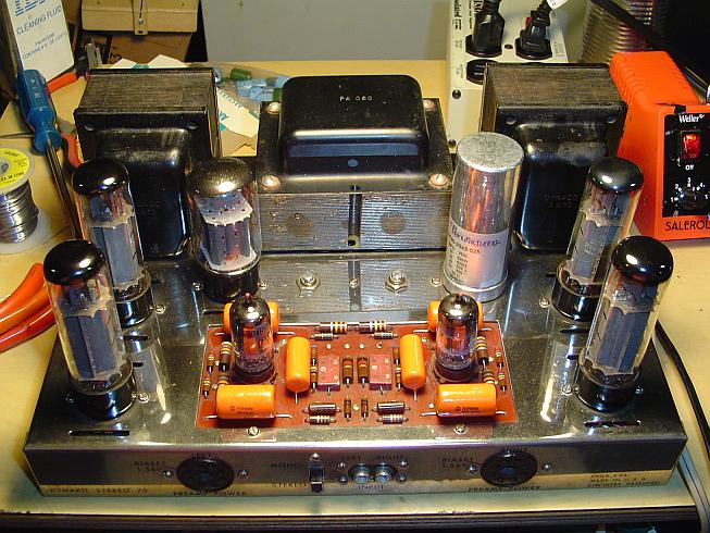
And here is my ST-70 with new capacitors in place.
Hope this helps,
Sal Brisindi
The bias selenium rectifier has nothing to do with the rectifer tube. If you look at a schematic of the ST-70 you will see a tap on the high voltage winding going to a diode, a couple of 10K resistors, 2 50uf capacitors and 2 5K potentiometers.
About the bias selenium rectifier and how I replaced it, attached is a photo. In the top photo you will see the bias selenium rectifier in between the 2 bias potentiometers before I replaced it.
In the second photo you will see I soldered a 1N4004 diode on a terminal strip. What I did was drill out the middle mounting post from the terminal strip and used that hole to mount the diode assembly to the same screw that held the original selenium rectifier which I left in place and removed the wires to it.
In the bottom photo you will see the diode screwed in with the old selenium rectifier and wires attached to the diode assembly.
And here is my ST-70 with new capacitors in place.
Hope this helps,
Sal Brisindi
-
Sal Brisindi - KT88
- Posts: 374
- Joined: Thu Mar 22, 2007 5:21 am
- Location: Freehold N.J.
![]() by Sal Brisindi » Sun Apr 01, 2007 8:52 pm
by Sal Brisindi » Sun Apr 01, 2007 8:52 pm
Sal Brisindi wrote:If you look at a schematic of the ST-70 you will see a tap on the high voltage winding going to a diode, a couple of 10K resistors, 2 50uf capacitors and 2 5K potentiometers.
Correction, 2 10 K potentiometers....
Sal Brisindi
-
Sal Brisindi - KT88
- Posts: 374
- Joined: Thu Mar 22, 2007 5:21 am
- Location: Freehold N.J.
![]() by wiredbecker » Sun Apr 01, 2007 10:30 pm
by wiredbecker » Sun Apr 01, 2007 10:30 pm
Sal Brisindi wrote:Sorry to hear about your wrist, you can go to Radio Shack and buy a left handed soldering iron.. Yellow_Light_Colorz_PDT_09
This made me laugh, thanks.
-
wiredbecker - KT88
- Posts: 301
- Joined: Mon Mar 26, 2007 3:48 pm
- Location: Albany Landfill, CA
![]() by erichayes » Sun Apr 01, 2007 10:58 pm
by erichayes » Sun Apr 01, 2007 10:58 pm
Hi All,
Even if the bias supply caps test OK for capacitance and leakage, I recommend replacing them with 100 µF @ 100 WV caps. Dynaco, unfortunately, opted to go with a tapped high voltage winding for deriving the bias, which eliminates the possibility of full wave rectification for the bias voltage. The next best thing is to increase the filter capacitance to minimize ripple.
As far as the replacement bias rectifier is concerned, there's no need to do anything fancy. Simply strap the silicon diode onto the selenium--observing proper polarity, of course. The banded end of the Si diode should be connected to the terminal going to the transformer lead; the other end goes to the remaining terminal. Selenium rectifiers, almost without exception (lightning strike?) never shorted--they opened up. Putting the silicon diode in parallel with an open selenium is the same as putting it across a terminal strip. And even if the selenium diode has a little poop left in it, the silicon's front to back ratio is so far superior it will still appear as if the selenium wasn't there.
Eric in the Jefferson State
- erichayes
- KT88
- Posts: 987
- Joined: Fri Jan 23, 2004 9:01 pm
- Location: McKinleyville CA
![]() by EWBrown » Mon Apr 02, 2007 5:09 am
by EWBrown » Mon Apr 02, 2007 5:09 am
A good way to get the performance enhancement of the cap board, and yet preserve the original looks, is to just leave the (disconnected) can cap in place, and install the cap board of choice, either the SDS or the C Chong board. Some of these cap boards have the bias circuitry included, and need only the two boas pots, the original caps and selenium rectifier can be removed.
Congrads on the restorations, and enjoy the tube sound!
/ed B inNH
Congrads on the restorations, and enjoy the tube sound!
/ed B inNH
Real Radios Glow in the Dark
-

EWBrown - Insulator & Iron Magnate
- Posts: 6389
- Joined: Wed Mar 19, 2003 6:03 am
- Location: Now located in Clay County, NC !
11 posts
• Page 1 of 1
Who is online
Users browsing this forum: No registered users and 106 guests