I have a preamp I'm working on currently. I measure 1.2mV AC on the output of the supply which is feeding the plates of a 6CG7 SRPP circuit. I have ~6.1V on my cathodes & 300V on my plates.
On the output cathode side of my 6CG7 tubes, I measure about the same 1.2mV AC ripple. On the other side of the coupling cap, I'm getting 4X that or 3-5mV. Any ideas?
I've posted something like this before, but turned out it was in the power supply.
Thanks for any ideas!
Blair
Different AC ripple on either side of preamp coupling cap
10 posts
• Page 1 of 1
Different AC ripple on either side of preamp coupling cap
![]() by Blair » Tue Jan 07, 2014 11:09 pm
by Blair » Tue Jan 07, 2014 11:09 pm
- Blair
- KT88
- Posts: 1272
- Joined: Thu Nov 09, 2006 10:22 am
Re: Different AC ripple on either side of preamp coupling ca
![]() by kheper » Wed Jan 08, 2014 6:43 am
by kheper » Wed Jan 08, 2014 6:43 am
The cap may be picking up AC hum or RF interference. You may want to switch to DC on the fils, shorten the leads on the cap or whatever.
-

kheper - KT88
- Posts: 1252
- Joined: Wed Dec 21, 2005 10:14 pm
- Location: Philly, PA
Re: Different AC ripple on either side of preamp coupling ca
![]() by DeathRex » Wed Jan 08, 2014 8:40 am
by DeathRex » Wed Jan 08, 2014 8:40 am
Gosh it's kinda hard to measure 1.2mv. Try an Aikido, the purpose of the second stage is to get rid of the 1.2mv.
Post a schematic.
Post a schematic.
At first I wanted to be a ET. Now I are one.
-

DeathRex - KT88
- Posts: 1014
- Joined: Wed Nov 18, 2009 8:13 pm
- Location: Cortez, CO
Re: Different AC ripple on either side of preamp coupling ca
![]() by Geek » Wed Jan 08, 2014 5:49 pm
by Geek » Wed Jan 08, 2014 5:49 pm
What's your psu schema look like 
-= Gregg =-
Fine wine comes in glass bottles, not plastic sacks. Therefore the finer electrons are also found in glass bottles.
Fine wine comes in glass bottles, not plastic sacks. Therefore the finer electrons are also found in glass bottles.
-

Geek - KT88
- Posts: 3585
- Joined: Sun Oct 21, 2007 3:01 am
- Location: Chilliwack, British Columbia
Re: Different AC ripple on either side of preamp coupling ca
![]() by Blair » Wed Jan 08, 2014 10:18 pm
by Blair » Wed Jan 08, 2014 10:18 pm
Hi guys,
It's a standard 6SN7 SRPP schematic with 1.5K cathode resistors. I added 1.8K stoppers on all grids. 1uF coupling caps on the output and 475K to ground after that. Sorry, I'm on a phone. My computer locked up:(
Anyway, the PS is a 6BW4 into 22uF -- 20H choke -- 68uf -- 5.6K -- 60uf
I moved things around and floated my filaments and now, I get a (muted input) .5mV settled on each channel into a 30K active load (cheapie receiver).
I have never been able to make a super quiet, tube rectified preamp.
One thing for sure. The NOS power transformer definitely puts out mechanical hum. That could be some of it.
- Blair
- KT88
- Posts: 1272
- Joined: Thu Nov 09, 2006 10:22 am
Re: Different AC ripple on either side of preamp coupling ca
![]() by Geek » Thu Jan 09, 2014 1:00 am
by Geek » Thu Jan 09, 2014 1:00 am
Hmmm, have you lifted the heaters or DC supplied them?
Better to cure the cause than mask the problem. Aikido is really a "fudge" than a fix, IMO
Cheers!
Better to cure the cause than mask the problem. Aikido is really a "fudge" than a fix, IMO
Cheers!
-= Gregg =-
Fine wine comes in glass bottles, not plastic sacks. Therefore the finer electrons are also found in glass bottles.
Fine wine comes in glass bottles, not plastic sacks. Therefore the finer electrons are also found in glass bottles.
-
Geek - KT88
- Posts: 3585
- Joined: Sun Oct 21, 2007 3:01 am
- Location: Chilliwack, British Columbia
Re: Different AC ripple on either side of preamp coupling ca
![]() by Blair » Thu Jan 09, 2014 7:10 am
by Blair » Thu Jan 09, 2014 7:10 am
Hi Gregg,
Yes, the heaters for the 8CG7s are sitting at 100V reference and the plates of the top tubes are at 309V.
Once my B+ settles, with my meter set on AC mV, it is at .5mV AC ripple, so there appears to be no real loss from the PS to the outputs now. You think adding another small cap section of 3-5uF may help right by the plates?
Thanks!
Blair
- Blair
- KT88
- Posts: 1272
- Joined: Thu Nov 09, 2006 10:22 am
Re: Different AC ripple on either side of preamp coupling ca
![]() by Geek » Thu Jan 09, 2014 8:36 am
by Geek » Thu Jan 09, 2014 8:36 am
Heya,
500uV of ripple on the B+ line is pretty good
So, the tubes are picking up ripple from somewheres.
- The lifted heaters, are they bypassed for AC with a 2.2-10uF cap to ground? That one bit me on a repair job! It hummed like crazy, but all voltages were good. Turned out to be a dry heater lift bypass cap
- Hummy tube (large h-k leakage). Westinghouse and Admiral brands are insane for that Try a different brand if available.
- Wiring layout.
- Ground loop.
Cheers!
500uV of ripple on the B+ line is pretty good
So, the tubes are picking up ripple from somewheres.
- The lifted heaters, are they bypassed for AC with a 2.2-10uF cap to ground? That one bit me on a repair job! It hummed like crazy, but all voltages were good. Turned out to be a dry heater lift bypass cap
- Hummy tube (large h-k leakage). Westinghouse and Admiral brands are insane for that
Try a different brand if available.- Wiring layout.
- Ground loop.
Cheers!
-= Gregg =-
Fine wine comes in glass bottles, not plastic sacks. Therefore the finer electrons are also found in glass bottles.
Fine wine comes in glass bottles, not plastic sacks. Therefore the finer electrons are also found in glass bottles.
-
Geek - KT88
- Posts: 3585
- Joined: Sun Oct 21, 2007 3:01 am
- Location: Chilliwack, British Columbia
Re: Different AC ripple on either side of preamp coupling ca
![]() by DeathRex » Thu Jan 09, 2014 8:43 am
by DeathRex » Thu Jan 09, 2014 8:43 am
I was just looking into this yesterday. Once you elevate the filaments, what size cap do you need on the DC going to the filaments? Most I've seen is 10uf.
At first I wanted to be a ET. Now I are one.
-
DeathRex - KT88
- Posts: 1014
- Joined: Wed Nov 18, 2009 8:13 pm
- Location: Cortez, CO
Re: Different AC ripple on either side of preamp coupling ca
![]() by Blair » Thu Jan 09, 2014 12:53 pm
by Blair » Thu Jan 09, 2014 12:53 pm
I usually use 1.2uf ploys there because they are cheap at surplus.
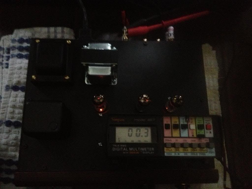
I moved things around and got between .3 and .5mV on the outputs.
Not sure if that is good enough or not. He has 80s model KG4 speakers. 94db. Mine are 91db. I can hear the power transformer over the audible hum in the speakers. That's the worst part about old stock. You never know what it's going to do under load:(
I moved things around and got between .3 and .5mV on the outputs.

Not sure if that is good enough or not. He has 80s model KG4 speakers. 94db. Mine are 91db. I can hear the power transformer over the audible hum in the speakers. That's the worst part about old stock. You never know what it's going to do under load:(
- Blair
- KT88
- Posts: 1272
- Joined: Thu Nov 09, 2006 10:22 am
10 posts
• Page 1 of 1
Who is online
Users browsing this forum: No registered users and 3 guests