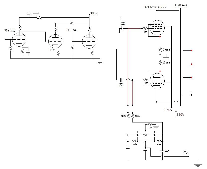
PPP 6CB5A schematic? Look OK?
I'm putting my current monster amps on hold for a while since the tubes alone are going to cost more than a college student's car:)
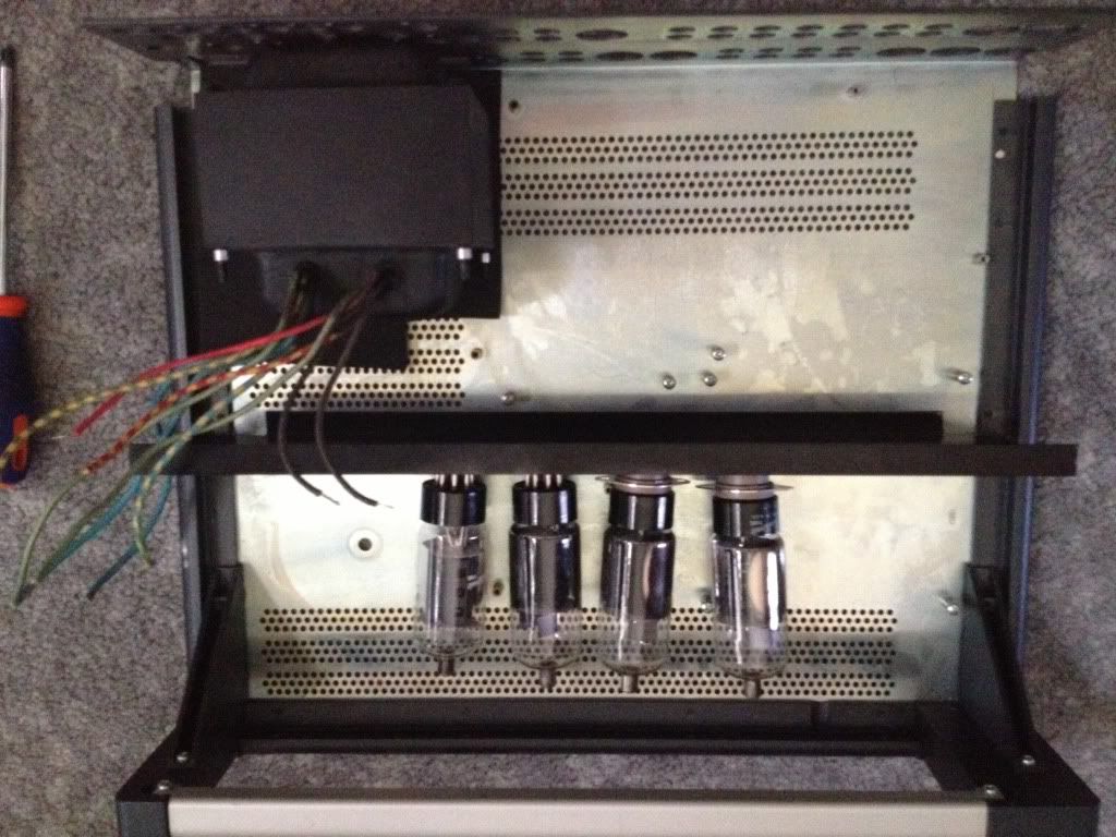
I have an octet of 6CB5As, a NOS sleeve of 6GF7A tubes, and some various 9 pins.
I can order 1.7K @ 100W Edcor output transformers, and I basically have the rest.
Does this look OK?
Thanks!
Blair
I have an octet of 6CB5As, a NOS sleeve of 6GF7A tubes, and some various 9 pins.
I can order 1.7K @ 100W Edcor output transformers, and I basically have the rest.
Does this look OK?
Thanks!
Blair