Bias balance pot?

ask your general tube related questions here

Bias balance pot?

Postby Blair » Sat Feb 09, 2013 9:20 pm

Can someone tell me why this does not work? Due to limited space on a recent project, I got the idea to use a single pot to make a variable fixed negative source and feed the circuit shown.

The variable negative source is just fine, but the circuit below does nothing when I turn the pot in either direction? Am I missing something?

Image

Shoot! Just noticed I did not note the pot value. It is a 10k.

Thanks!

Blair
Blair
KT88
 
Posts: 1272
Joined: Thu Nov 09, 2006 10:22 am

Re: Bias balance pot?

Postby battradio » Sun Feb 10, 2013 12:14 am

Hi Blair ,

Its not reference to ground no mater what size pot you have no current is being drawn so there is no voltage change try it like Shannons ST 70
http://www.diytube.com/st70/diytube_st70_B.pdf
Mark
Image
User avatar
battradio
KT88
 
Posts: 927
Joined: Tue Mar 10, 2009 12:58 am
Location: near ST.Louis MO.

Re: Bias balance pot?

Postby Tubeamp » Sun Feb 17, 2013 2:21 pm

Hi Blair, you may add 2 resistors let say 47K each. Connect the one side of the first 47K resistor at the junction of the existing 100K res and the top end of the pot and ground the other side . Connect the second 47 K res at the junction of the other existing 100K res and the bottom end of the pot and ground the other side. A current will flow through the pot and the added 47K resistors giving you a potential divider on either side of the pot. Perhaps you will need more negative bias voltage at the pot wiper .
User avatar
Tubeamp
 
Posts: 71
Joined: Sun Jul 18, 2010 3:41 am
Location: Cyprus

Re: Bias balance pot?

Postby Blair » Sun Feb 17, 2013 10:16 pm

Thanks!

Ill give it a shot. I tried grounding the 10K like the ST-70 through a 1 meg, and it worked, but offered very little adjustment.

Blair
Blair
KT88
 
Posts: 1272
Joined: Thu Nov 09, 2006 10:22 am

Re: Bias balance pot?

Postby Tubeamp » Sun Feb 17, 2013 10:27 pm

The ST-70 is using a 500k pot instead a 10K in your case. According to your schematic you might need to increase the pot value and probably you will need to increase the negative bias from -24V to -30V or what would be necessary.
User avatar
Tubeamp
 
Posts: 71
Joined: Sun Jul 18, 2010 3:41 am
Location: Cyprus

Re: Bias balance pot?

Postby Blair » Sun Feb 17, 2013 10:37 pm

That's true.

Then, I thought about doing it like some of the old amps where the center of the pot is grounded and each cathode is at either end of the pot. Changing it to a 20-30 ohm pot.

Blair
Blair
KT88
 
Posts: 1272
Joined: Thu Nov 09, 2006 10:22 am

Re: Bias balance pot?

Postby Blair » Tue Mar 12, 2013 2:42 pm

I got to tinkering with this project again and rewired it for 7591 output tubes because the driver could not push the 6L6 past around 7-10W.

Now I am back to the bias balance item. Is there anything wiring with this:

http://www.rru.com/~meo/Guitar/Amps/Kal ... schem.html

Like in the first amp schematic with say a 25 ohm pot with each leg going to a cathode for balance?

Thanks!

Blair
Blair
KT88
 
Posts: 1272
Joined: Thu Nov 09, 2006 10:22 am

Re: Bias balance pot?

Postby DeathRex » Tue Mar 12, 2013 4:19 pm

For a balanced negative bias: http://ampslab.com/SCHEMATICS/EicoHF5060.gif

Do you have a full schemtic of your amp?
At first I wanted to be a ET. Now I are one.
User avatar
DeathRex
KT88
 
Posts: 1014
Joined: Wed Nov 18, 2009 8:13 pm
Location: Cortez, CO

Re: Bias balance pot?

Postby battradio » Tue Mar 12, 2013 4:22 pm

it's leaving the fixed bias set and adding , a small amount of cathode bias to balance the tube current ,by shifting the amount of cathode bias with the pot .
Mark
Image
User avatar
battradio
KT88
 
Posts: 927
Joined: Tue Mar 10, 2009 12:58 am
Location: near ST.Louis MO.

Re: Bias balance pot?

Postby Blair » Tue Mar 12, 2013 6:52 pm

Thanks guys!

This is perfect and uses the 10K pots installed.

I will give it a go.

Blair
Blair
KT88
 
Posts: 1272
Joined: Thu Nov 09, 2006 10:22 am

Re: Bias balance pot?

Postby DeathRex » Tue Mar 12, 2013 8:29 pm

The balance adjust is 10K, the bias adjust is 50K. If both of yours are 10K, decrease the 100K to ground to 22K. Otherwise a 10K will do very little. Make sure you get enough negative bias voltage with the tubes out first.
At first I wanted to be a ET. Now I are one.
User avatar
DeathRex
KT88
 
Posts: 1014
Joined: Wed Nov 18, 2009 8:13 pm
Location: Cortez, CO

Re: Bias balance pot?

Postby Blair » Sat Mar 23, 2013 7:44 am

This worked just fine. Thanks guys! I ended up with 47K to ground. I was able to balance the bias out pretty well.

Here is the drawn schematic. I'm running into an issue with drive voltage. I'm peaking out at around 20-21V before clipping.

Image

I get a clean 12-15W, but the 7591 should easily deliver around 2X that at 400V.

Any ideas? Can I drop a 12AX7 in place of the 7247 in this circuit to see if it fixed the drive voltage? The tubes drawn here are 7247 and 7591s. Sorry, I forgot to pencil that in:)

I can draw the PS if needed.

Thanks!

Blair
Blair
KT88
 
Posts: 1272
Joined: Thu Nov 09, 2006 10:22 am

Re: Bias balance pot?

Postby EWBrown » Sun Mar 24, 2013 9:01 pm

What are the voltages on the 7247 pins 6 and 8 (plate and cathode)? You may be simply running out of signal "headroom" in the VA stage.
The voltage across the 1K VA stage's cathode resistor will be the major input-signal-voltage limiting factor here. I'm guessing the stage has
a 0.4 to 0.7 mA cathode current, (with the 150 and 270K resistors in series with the plate) which translates to 0.4 to 0.7 V across the RK,
and that means that any input voltages above that level, will be clipped, before it reaches the PI stage's grid.

Image

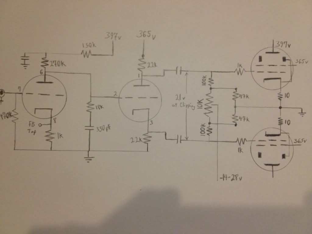
For the 7591s you may need more signal gain than the triode stage can supply, the 7247 is sufficient for the ST35, as it needs to deliver only approx
+/- 14V pk-pk to the EL84 control grids, and the 7591 would be running only about 40 to 50% of maximum power output with 21V (or 20-30% with 14V).
Closer to +/- 28 to 32V pk would be required to achieve full power with 7591s.

The PI stage (pins 1, 2, 3) has only a gain of 1, or slightly less, changing it to a higher gain triode wouldn't develop any higher gain in that stage.
It is essentially a "split" cathode follower, which means it has no voltage gain, though it can have current gain.

A 12AX7 "drop in" wouldn't be advisable, with the PI stage's 22K RA and RK, the maximum safe plate current would be significantly exceeded.

You may have to use a pentode for the first VA gain stage, as is done with the 7868 (similar to 7591 and 6GM5) amp design,
in the back section of the RCA tube handbook.

Plan "B", which would be a major re-design, would be to use the triode gain stage, followed by a Schmidt or similar LTPI,
like Shannon's Poseidon or ST-70 driver. That circuit uses all triodes, and has more than enough overall gain to drive the 7951s. .

HTH

/ed B
Real Radios Glow in the Dark
User avatar
EWBrown
Insulator & Iron Magnate
 
Posts: 6389
Joined: Wed Mar 19, 2003 6:03 am
Location: Now located in Clay County, NC !

Re: Bias balance pot?

Postby Blair » Mon Mar 25, 2013 9:13 pm

Hi Ed,

Thanks! I gave up. I pulled the drill out today and went to hacking on my chassis.

I cut two more holes to add a "proper" VA/PI stage. I will probably do Shannon's ST-70 front end because I have an A$$ ton the 334Zs, or at least access to them.

That should swing these 7591s to 20W:)
Blair
KT88
 
Posts: 1272
Joined: Thu Nov 09, 2006 10:22 am

Re: Bias balance pot?

Postby battradio » Tue Mar 26, 2013 7:20 am

Shannon's front end would swing a T-Rex by the tail , it will drive KT120 to 100 watts
Mark
Image
User avatar
battradio
KT88
 
Posts: 927
Joined: Tue Mar 10, 2009 12:58 am
Location: near ST.Louis MO.

Next

Return to tube 101

Who is online

Users browsing this forum: No registered users and 38 guests