ST-70 rebuild concept?

ask your general tube related questions here

Re: ST-70 rebuild concept?

Postby Blair » Tue Dec 11, 2012 1:17 pm

Thanks 20,

I tried various levels of feedback, but it sounds best without it really. It seems to lose some bass response when FB is injected.

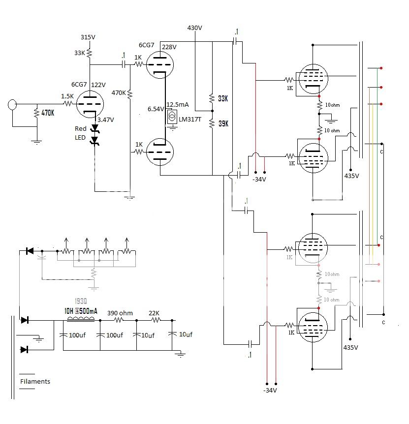
Here is essentially the topology I am using. The FB is injected on the cathode of the lower triode of the PI.
Image
Blair
KT88
 
Posts: 1272
Joined: Thu Nov 09, 2006 10:22 am

Re: ST-70 rebuild concept?

Postby 20to20 » Tue Dec 11, 2012 1:38 pm

Blair wrote:Thanks 20,

I tried various levels of feedback, but it sounds best without it really. It seems to lose some bass response when FB is injected.

Here is essentially the topology I am using. The FB is injected on the cathode of the lower triode of the PI.


Your diagram shows it going to the grid. If you did use the cathode, then the constant current source may be affecting it if not negating it. Try the cathode of the driver. It's unbypassed, as drawn.

20
Headed for Tishomingo to sing in a can...
User avatar
20to20
KT88
 
Posts: 566
Joined: Wed Apr 21, 2010 1:48 pm
Location: W-S, NC

Re: ST-70 rebuild concept?

Postby Blair » Tue Dec 11, 2012 1:45 pm

I'm sorry, yes it is the grid I injected the NFB into.

I see most NFB injected between the cathode resistor and a series 100 ohm resistor on the VA stage. Should I add the 100 ohm resistor in series?

Blair
Blair
KT88
 
Posts: 1272
Joined: Thu Nov 09, 2006 10:22 am

Re: ST-70 rebuild concept?

Postby 20to20 » Tue Dec 11, 2012 4:45 pm

Blair wrote:I'm sorry, yes it is the grid I injected the NFB into.

I see most NFB injected between the cathode resistor and a series 100 ohm resistor on the VA stage. Should I add the 100 ohm resistor in series?

Blair


My thoughts, not knowing the source of your design elements,

Let me start with the grid injection. If you are following a proven design, I'd try to make that work right first. I can't say whether that is better or otherwise from cathode injection.

As far as the "sound" with FB goes, keep in mind (I discovered this with my new build) that the open loop FR of your amp probably drops dramaticaly from about 10K out, so it may sound "good" "OK" "normal" that way, but when you add FB the FR goes flat farther into the highs which gives the illusion of less bass, when in reality it is more realistic treble. The overall gain will be less and make the amp sound less powerfull, of course.

As far as cathode injection goes, I've seen it go in at the cathode above the resistor, I've seen it injected between two resistors like you're suggesting. But look at the ST-70 and you'll see 47R under the injection point so it's all about the precise design goals that dictate that. FR tailoring in the design and gain of the amp is what ultimately fixes those component values. I can't do the algebra using your design to give you input sensitivity/gain/FR/distortion/FB signal balance. Those are parameters for you to come up with.

One of the first things to decide after you set your power output goals is to set the input sensitivity goal (.25v, .5v., .75., 1.3v....??) and then the gain of the amp falls into the next set of decisions. In the ST-70 the open loop gain is 125 @ 1.3v input into 8R. Figure out what the output power would be under those conditions and you'll see why FB is necessary to cut the gain.

Good Luck! (b) (b)
Headed for Tishomingo to sing in a can...
User avatar
20to20
KT88
 
Posts: 566
Joined: Wed Apr 21, 2010 1:48 pm
Location: W-S, NC

Re: ST-70 rebuild concept?

Postby DeathRex » Tue Dec 11, 2012 6:04 pm

Wouldn't that type of feedback affect the lower EL34 more that the upper EL34?
And wouldn't you need much more feedback? I'd like to hear what the difference is betwen the 6CG7's grid and the 6DJ8's cathode.
At first I wanted to be a ET. Now I are one.
User avatar
DeathRex
KT88
 
Posts: 1014
Joined: Wed Nov 18, 2009 8:13 pm
Location: Cortez, CO

Re: ST-70 rebuild concept?

Postby Blair » Tue Dec 11, 2012 9:49 pm

I thought the same thing about the lower triode cathode injection point. It seemed to work fine on an amp I built, but I'd rather try to inject it at the VA stage because it is the most common method.

I'll try to get a working schematic drawn up soon so it is easier to see everything.

Thanks!

Blair
Blair
KT88
 
Posts: 1272
Joined: Thu Nov 09, 2006 10:22 am

Re: ST-70 rebuild concept?

Postby Blair » Wed Dec 12, 2012 11:01 am

OK guys,

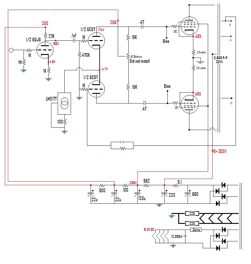
Here is an actual working schematic of what I have done:

Image

I still do not like what the feedback does to the amp. I understand the illusion of less bass due to freq extension, but I am playing a song that has a few solid 30hz notes at the very beginning, and with no feedback, it's there. With it, it sounds extremely distorted and "out of breath". I'm also wondering about adding a few hundred uF of filter after the choke to "stiffen" the PS.

How do my voltages look? I just added the LED string this AM. A little more gain, but it sounds nice.

Thanks!
Blair
Blair
KT88
 
Posts: 1272
Joined: Thu Nov 09, 2006 10:22 am

Re: ST-70 rebuild concept?

Postby 20to20 » Wed Dec 12, 2012 11:27 am

Blair wrote: I understand the illusion of less bass due to freq extension, but I am playing a song that has a few solid 30hz notes at the very beginning, and with no feedback, it's there. With it, it sounds extremely distorted and "out of breath". I'm also wondering about adding a few hundred uF of filter after the choke to "stiffen" the PS.

Thanks!
Blair


I understand the illusion of less bass due to freq extension,


The other factor I didn't mention on the bass end of the FR was that you could very possibly also have a high peak on the LF end that gets flattened with the FB. So, until you see what you have on a scope you won't really know what's coming through vis-a-vis the original quality of the source material. Do you have a frequency counter to use?

Although, being familiar with the source material through other gear will always be helpful without test equipment.

Good Luck!
Headed for Tishomingo to sing in a can...
User avatar
20to20
KT88
 
Posts: 566
Joined: Wed Apr 21, 2010 1:48 pm
Location: W-S, NC

Re: ST-70 rebuild concept?

Postby 20to20 » Wed Dec 12, 2012 12:45 pm

Blair,

What are the R values of your bias pots and the tail resistor?
Headed for Tishomingo to sing in a can...
User avatar
20to20
KT88
 
Posts: 566
Joined: Wed Apr 21, 2010 1:48 pm
Location: W-S, NC

Re: ST-70 rebuild concept?

Postby Blair » Wed Dec 12, 2012 1:32 pm

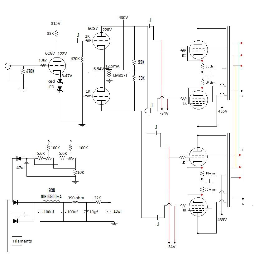
10k pots and the resistor to ground is 10K as well if I remember correctly.
Blair
KT88
 
Posts: 1272
Joined: Thu Nov 09, 2006 10:22 am

Re: ST-70 rebuild concept?

Postby 20to20 » Wed Dec 12, 2012 1:45 pm

Blair wrote:10k pots and the resistor to ground is 10K as well if I remember correctly.

If the pots are centered then you have only 10K between grids and only 15K to ground. On the ST-70 there is over 500K between grids and filtering there too. You have no filtering between grids and then only 5K to the filter from the grid. You need 270K in between everything to follow the ST-70 biasing circuit. You must be getting a ton of offsetting signal crosstalk from grid to grid.

With 5K on one side of the pot to the filter and 15K to ground on the other your grid input Z is going to be about 3K and the rolloff 3db point with a .1uf coupling cap is about 500Hz.

And what's the voltage on the input to your bias pots? You could have a lot of current through the tail R.
Headed for Tishomingo to sing in a can...
User avatar
20to20
KT88
 
Posts: 566
Joined: Wed Apr 21, 2010 1:48 pm
Location: W-S, NC

Re: ST-70 rebuild concept?

Postby Blair » Wed Dec 12, 2012 2:40 pm

Here is the bias schematic. Just for two pots. There are two sets just like this.

Image

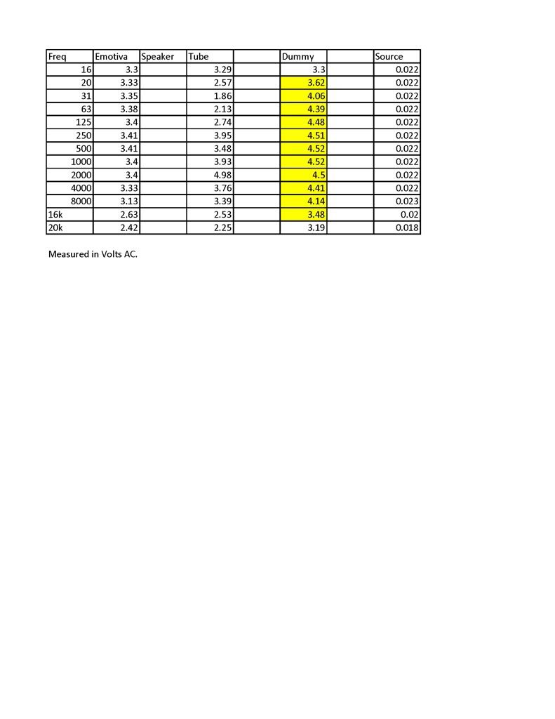
The roll offs appear to start to occur at 250hz and around 8-10K.
Blair
KT88
 
Posts: 1272
Joined: Thu Nov 09, 2006 10:22 am

Re: ST-70 rebuild concept?

Postby Blair » Wed Dec 12, 2012 4:58 pm

Here are some test results. I hope it is legible.

Image
Blair
KT88
 
Posts: 1272
Joined: Thu Nov 09, 2006 10:22 am

Re: ST-70 rebuild concept?

Postby dcriner » Fri Dec 28, 2012 2:42 pm

Paralleling power xfmrs runs the risk of circulating currents if the two xfmrs are not exactly identical. Even two of the same model might have some electrical differences.
Doug Criner
dcriner
KT88
 
Posts: 309
Joined: Mon Oct 23, 2006 4:19 pm
Location: Illinois

Re: ST-70 rebuild concept?

Postby Blair » Fri Dec 28, 2012 2:56 pm

Hi,

I did not parallel power transformers. Just the secondary of the output transformers.
Blair
KT88
 
Posts: 1272
Joined: Thu Nov 09, 2006 10:22 am

Previous

Return to tube 101

Who is online

Users browsing this forum: No registered users and 31 guests