ST-70 rebuild concept?

ask your general tube related questions here

Re: ST-70 rebuild concept?

Postby kheper » Sun Dec 09, 2012 5:50 pm

Blair wrote:OK.

Playing now. Here are my voltages:

EL34:
Pin 3 - 433V
Pin 4 - 435V


Nice voltage for EL34s. What is the voltage on pin 8?

VA Stage 6H30:

Plate 184V plate resistor 28.8K
Cathode 11.7V with 1.5K resistor


8ma * 184 = 1.5W

Also looks good.
User avatar
kheper
KT88
 
Posts: 1252
Joined: Wed Dec 21, 2005 10:14 pm
Location: Philly, PA

Re: ST-70 rebuild concept?

Postby Blair » Sun Dec 09, 2012 9:19 pm

Thanks! I've never seen cathode voltage that high. It seemed like it was being run really hot!

Pin 8 is .5V on all 4 tubes. Of course, the negative voltage is different for each tube to get .5V

The 6CG7 looks OK too?

Here is my sloppy, but functional wiring:

Image

Image
Blair
KT88
 
Posts: 1272
Joined: Thu Nov 09, 2006 10:22 am

Re: ST-70 rebuild concept?

Postby battradio » Mon Dec 10, 2012 5:16 am

Well how does it sound and when do you need the second set of output transformers ?
Mark
Image
User avatar
battradio
KT88
 
Posts: 927
Joined: Tue Mar 10, 2009 12:58 am
Location: near ST.Louis MO.

Re: ST-70 rebuild concept?

Postby Blair » Mon Dec 10, 2012 6:27 am

It sounds pretty good on initial impression. I'll try to run a few tests soon. Literally 15 minutes after I got it up on this tool box, I managed to trip and almost dislocated my left shoulder, so I will not be able to move it for a few days. I probably will not get to the other one until after the first of the year.

I think I might have found you a piece of metal. I can probably machine it with a bad shoulder:)

Blair
Blair
KT88
 
Posts: 1272
Joined: Thu Nov 09, 2006 10:22 am

Re: ST-70 rebuild concept?

Postby Blair » Mon Dec 10, 2012 3:07 pm

I ditched the 6H30. It acted very unstable and both that I have are fairly noisy. I had some wicked 120hz artifacts.

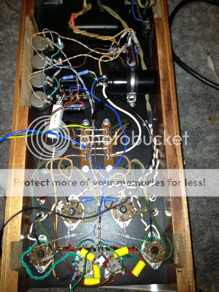
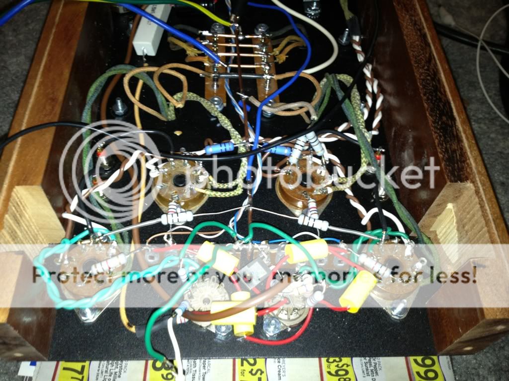
I swapped plate resistors, changed my cathode resistor, dropped a 6CG7 in and away went the noise and wobbly sine waves.

Now have 172V on my plate and 6.3V on my cathode along with a quiet amp.

I got the 6H30s from a buddy, so god knows what they went through.

Thanks!

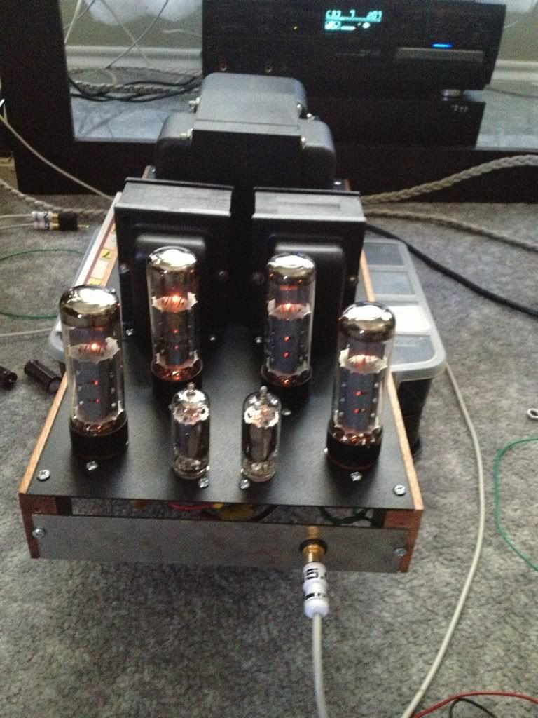
Ready for the joke? All this chassis work and a pretty nice looking amp? Notice the sweet faceplate? It's there because I forgot to drill a hole for an input:) I'm debating whether to drill out the back panel for the input or to drill the tiger maple for a front input.

Image
Blair
KT88
 
Posts: 1272
Joined: Thu Nov 09, 2006 10:22 am

Re: ST-70 rebuild concept?

Postby kheper » Mon Dec 10, 2012 3:28 pm

Looks good. Electro-Harmonix and Sovtek currently produce the 6H30, if you want to go back. They are not cheap, however.
User avatar
kheper
KT88
 
Posts: 1252
Joined: Wed Dec 21, 2005 10:14 pm
Location: Philly, PA

Re: ST-70 rebuild concept?

Postby Blair » Mon Dec 10, 2012 4:20 pm

Thanks,

The tube selection was not critical. Just what I had here, so I'm just as happy with the 6CG7. It sounds nice. I was getting ready to do some sine waves into a dummy load to figure out where I get onset clipping, but my 9V died in my meter.

Blair
Blair
KT88
 
Posts: 1272
Joined: Thu Nov 09, 2006 10:22 am

Re: ST-70 rebuild concept?

Postby Blair » Mon Dec 10, 2012 5:56 pm

I get roughly 22.3V at 1K before clipping, so it is roughly 60-65W which is what I expected. Makes nice clean waves up to that point. Not too shabby. I'll try to get it on a distortion analyzer soon at my friend's house to see how that looks. This is all, of course with no NFB. I'm still not sure how to implement it.

Blair
Blair
KT88
 
Posts: 1272
Joined: Thu Nov 09, 2006 10:22 am

Re: ST-70 rebuild concept?

Postby 20to20 » Mon Dec 10, 2012 8:24 pm

Blair wrote:I get roughly 22.3V at 1K before clipping, so it is roughly 60-65W which is what I expected. Makes nice clean waves up to that point. Not too shabby. I'll try to get it on a distortion analyzer soon at my friend's house to see how that looks. This is all, of course with no NFB. I'm still not sure how to implement it.

Blair


How much input signal did it take to get the 22v? What did you make your dummy load with?
Headed for Tishomingo to sing in a can...
User avatar
20to20
KT88
 
Posts: 566
Joined: Wed Apr 21, 2010 1:48 pm
Location: W-S, NC

Re: ST-70 rebuild concept?

Postby Blair » Mon Dec 10, 2012 8:32 pm

I'll have to measure the input signal tomorrow. It is fairly high though. About 2/3 volume from my SS preamp, so I would guess around 7V.

My dummy load measure 7.5ohms hot. It is 5 X 35Ohm non inductive resistors.

Somewhere I have a 4 ohm 100W resistor load, but I cannot find it right now.
Blair
Blair
KT88
 
Posts: 1272
Joined: Thu Nov 09, 2006 10:22 am

Re: ST-70 rebuild concept?

Postby 20to20 » Mon Dec 10, 2012 10:29 pm

Blair wrote:I'll have to measure the input signal tomorrow. It is fairly high though. About 2/3 volume from my SS preamp, so I would guess around 7V.


Did you mean .7v?

7v. would be again of @ 3. With a K voltage of 6.3v. you won't have any room for a larger drive signal. So you won't have anything left to give the input if you wire in some FB. You'll go backward on power output with the loss from FB.

20
Headed for Tishomingo to sing in a can...
User avatar
20to20
KT88
 
Posts: 566
Joined: Wed Apr 21, 2010 1:48 pm
Location: W-S, NC

Re: ST-70 rebuild concept?

Postby Blair » Mon Dec 10, 2012 10:40 pm

I'll check tomorrow.

I do think the gain is fairly low though.
Blair
KT88
 
Posts: 1272
Joined: Thu Nov 09, 2006 10:22 am

Re: ST-70 rebuild concept?

Postby Blair » Tue Dec 11, 2012 8:37 am

OK, I forget I am using my phone as a signal generator, do its better than I thought. The input voltage is around .35V at full power.

The clipping occurs around 62-65W. Running back through the circuit, the VA stage clips at a much higher input voltage, but the phase inverter seems to clip around the same input voltage as my output. At least very close.

Should I essentially take the ST-70 feedback resistor value and half it? I'm still not sure how this is going to work with two output transformers in parallel.

Thanks!

Blair
Blair
KT88
 
Posts: 1272
Joined: Thu Nov 09, 2006 10:22 am

Re: ST-70 rebuild concept?

Postby battradio » Tue Dec 11, 2012 8:53 am

Start with the same value , the voltages of of the transformer will be the same even though the impeadance is half .
Mark
Image
User avatar
battradio
KT88
 
Posts: 927
Joined: Tue Mar 10, 2009 12:58 am
Location: near ST.Louis MO.

Re: ST-70 rebuild concept?

Postby 20to20 » Tue Dec 11, 2012 9:09 am

Blair wrote:Should I essentially take the ST-70 feedback resistor value and half it? I'm still not sure how this is going to work with two output transformers in parallel.

Blair


You don't have an ST-70 circuit so I wouldn't try to reference anything from that. The fact of two trannies won't matter. The object is to get the correct amount of FB. So think of the feedback signal as anti-signal. The lower the value of resistor the more anti-signal. And the resistor value is going to influence the injection point current since it goes back to the tranny and ground.

I would put a 10K-50K pot ( plus a safety resistor that will keep the cathode from going to ground if you turn the pot to 0) in there and fine tune it to find the final value. You have to customize it for this circuit.

(1) So you have to pick your point of injection. Driver cathode? Are you going to bypass it? Don't kill the FB with the bypassing.

(2) Realize that the parallel resistance is going to change the biasing of the driver so raise the cathode resistor value to get the right parallel value back. Do the parallel resistance calculation to keep the proper voltage.
Headed for Tishomingo to sing in a can...
User avatar
20to20
KT88
 
Posts: 566
Joined: Wed Apr 21, 2010 1:48 pm
Location: W-S, NC

PreviousNext

Return to tube 101

Who is online

Users browsing this forum: No registered users and 31 guests