I tried various levels of feedback, but it sounds best without it really. It seems to lose some bass response when FB is injected.
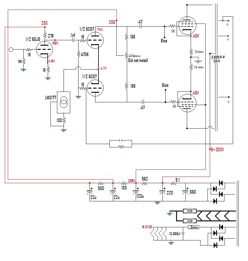
Here is essentially the topology I am using. The FB is injected on the cathode of the lower triode of the PI.
![]() by Blair » Tue Dec 11, 2012 1:17 pm
by Blair » Tue Dec 11, 2012 1:17 pm
![]() by 20to20 » Tue Dec 11, 2012 1:38 pm
by 20to20 » Tue Dec 11, 2012 1:38 pm
Blair wrote:Thanks 20,
I tried various levels of feedback, but it sounds best without it really. It seems to lose some bass response when FB is injected.
Here is essentially the topology I am using. The FB is injected on the cathode of the lower triode of the PI.

![]() by Blair » Tue Dec 11, 2012 1:45 pm
by Blair » Tue Dec 11, 2012 1:45 pm
![]() by 20to20 » Tue Dec 11, 2012 4:45 pm
by 20to20 » Tue Dec 11, 2012 4:45 pm
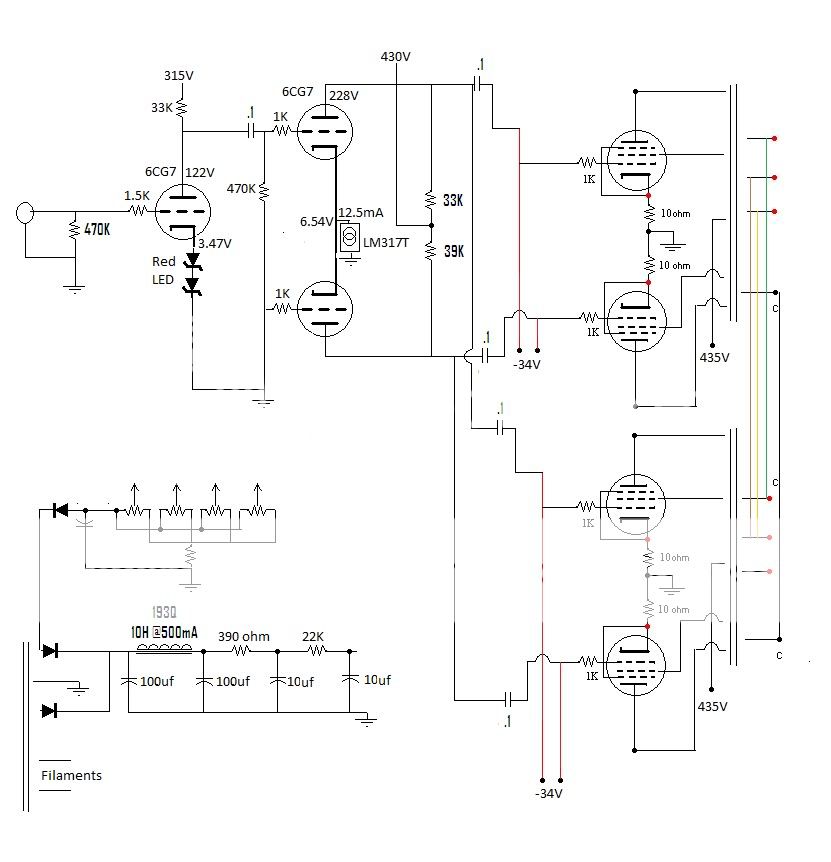
Blair wrote:I'm sorry, yes it is the grid I injected the NFB into.
I see most NFB injected between the cathode resistor and a series 100 ohm resistor on the VA stage. Should I add the 100 ohm resistor in series?
Blair

![]() by DeathRex » Tue Dec 11, 2012 6:04 pm
by DeathRex » Tue Dec 11, 2012 6:04 pm

![]() by Blair » Tue Dec 11, 2012 9:49 pm
by Blair » Tue Dec 11, 2012 9:49 pm
![]() by Blair » Wed Dec 12, 2012 11:01 am
by Blair » Wed Dec 12, 2012 11:01 am
![]() by 20to20 » Wed Dec 12, 2012 11:27 am
by 20to20 » Wed Dec 12, 2012 11:27 am
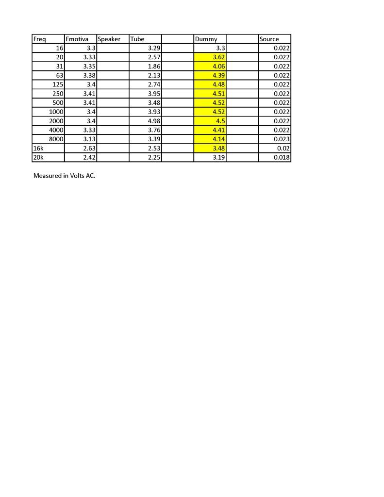
Blair wrote: I understand the illusion of less bass due to freq extension, but I am playing a song that has a few solid 30hz notes at the very beginning, and with no feedback, it's there. With it, it sounds extremely distorted and "out of breath". I'm also wondering about adding a few hundred uF of filter after the choke to "stiffen" the PS.
Thanks!
Blair
I understand the illusion of less bass due to freq extension,
![]() by 20to20 » Wed Dec 12, 2012 12:45 pm
by 20to20 » Wed Dec 12, 2012 12:45 pm
![]() by Blair » Wed Dec 12, 2012 1:32 pm
by Blair » Wed Dec 12, 2012 1:32 pm
![]() by 20to20 » Wed Dec 12, 2012 1:45 pm
by 20to20 » Wed Dec 12, 2012 1:45 pm
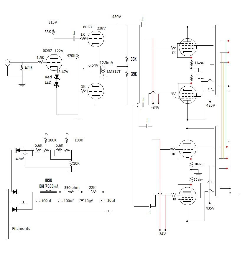
Blair wrote:10k pots and the resistor to ground is 10K as well if I remember correctly.
![]() by Blair » Wed Dec 12, 2012 2:40 pm
by Blair » Wed Dec 12, 2012 2:40 pm
![]() by Blair » Wed Dec 12, 2012 4:58 pm
by Blair » Wed Dec 12, 2012 4:58 pm
![]() by dcriner » Fri Dec 28, 2012 2:42 pm
by dcriner » Fri Dec 28, 2012 2:42 pm
![]() by Blair » Fri Dec 28, 2012 2:56 pm
by Blair » Fri Dec 28, 2012 2:56 pm
Users browsing this forum: No registered users and 56 guests