Hi Mark,
I have. I was in hopes to get it all on one chassis, but it isn't looking like it will all fit.
That would free up space for a more conventional layout, etc.
It's also a bit scary to use an umbilical with almost 700V riding on it.
Blair
Bogen MO-200A conversion
54 posts
• Page 3 of 4 • 1, 2, 3, 4
![]() by Blair » Sun Sep 02, 2012 1:44 pm
by Blair » Sun Sep 02, 2012 1:44 pm
Still looking at the PS in the original bogen amp, and I see no filtering besides the two 100uF caps in the doubler. I sim'd this in PSD II, and I get a secondary of about 325V under a 250mA load to get the 680V B+ in the original amp design.
So, I asked the other day if the caps in the doubler need to be full B+ voltage because Bogen used 450V caps. It was recommended that I use caps that will handle full B+. the issue is finding sizable caps that will handle 800v.
A few things while playing in PSD II.
If I use poly caps in the doubler (20uF), it drops my B+ to around 520V. Is there an issue with 20UF caps there? That is a much better B+ to buy caps for!
Another option, assuming the secondary is really 325V, is just a FWB for a B+ of around 410V. At 410V, is there a possibility that I will not get 100W out of a quad of tubes?
If dropping the doubler caps to "tune" the B+ is not harmful, it seems like a good option.
Thanks!
Blair
- Blair
- KT88
- Posts: 1272
- Joined: Thu Nov 09, 2006 10:22 am
![]() by kheper » Sun Sep 02, 2012 7:04 pm
by kheper » Sun Sep 02, 2012 7:04 pm
Blair wrote:
So, I asked the other day if the caps in the doubler need to be full B+ voltage because Bogen used 450V caps. It was recommended that I use caps that will handle full B+. the issue is finding sizable caps that will handle 800v.
Look at C9 and C10. They are (2) 450V caps in series, providing for a max V of 900. Look at the voltage coming off of C9. To me, it looks like 640 V (or 680 V).
Another option, assuming the secondary is really 325V, is just a FWB for a B+ of around 410V. At 410V, is there a possibility that I will not get 100W out of a quad of tubes?
Blair
I suspect your secondary is only 230-250 V.
-

kheper - KT88
- Posts: 1252
- Joined: Wed Dec 21, 2005 10:14 pm
- Location: Philly, PA
![]() by Blair » Sun Sep 02, 2012 7:26 pm
by Blair » Sun Sep 02, 2012 7:26 pm
Thanks Joe,
Sorry, I've never really done anything with doublers. It makes perfect sense to me because the lower leg of the transformer is at 1/2 B+, and the top cap sits at 660v, but since it is in series it can handle the full voltage.
This helps a bunch!
Blair
Sorry, I've never really done anything with doublers. It makes perfect sense to me because the lower leg of the transformer is at 1/2 B+, and the top cap sits at 660v, but since it is in series it can handle the full voltage.
This helps a bunch!
Blair
- Blair
- KT88
- Posts: 1272
- Joined: Thu Nov 09, 2006 10:22 am
![]() by kheper » Mon Sep 03, 2012 8:39 am
by kheper » Mon Sep 03, 2012 8:39 am
Blair wrote:Still looking at the PS in the original bogen amp, and I see no filtering besides the two 100uF caps in the doubler
http://tubes.nekhbet.com/#fil
The minimum PS filter capacitance advised for an amp with that much power and high B+ is ~460uF.
You mentioned adding a choke without additional filtering. That Bogen model was a PA. To convert it into a hi-fi, a choke and more filter caps in the supply is recommended. See the doubler/choke in the 211 schemo:
http://www.bonavolta.ch/hobby/en/audio/211_1.htm
-
kheper - KT88
- Posts: 1252
- Joined: Wed Dec 21, 2005 10:14 pm
- Location: Philly, PA
![]() by Blair » Mon Sep 03, 2012 9:07 am
by Blair » Mon Sep 03, 2012 9:07 am
Thanks Joe!
Now that I saw your post, I will be able to add quite tha amount of capacitance and choke.
Will this work as a grid choke to feed all 8 G2 screen grids?
http://item.mobileweb.ebay.com/viewitem ... 0460308248
It says 70mA, so I would think so.
Thanks!
Blair
Now that I saw your post, I will be able to add quite tha amount of capacitance and choke.
Will this work as a grid choke to feed all 8 G2 screen grids?
http://item.mobileweb.ebay.com/viewitem ... 0460308248
It says 70mA, so I would think so.
Thanks!
Blair
- Blair
- KT88
- Posts: 1272
- Joined: Thu Nov 09, 2006 10:22 am
![]() by Blair » Mon Sep 03, 2012 9:16 am
by Blair » Mon Sep 03, 2012 9:16 am
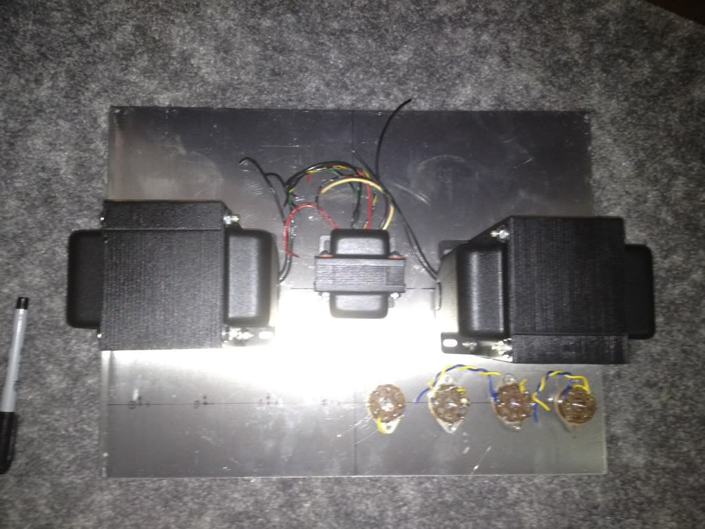
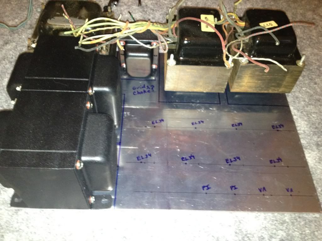
I confirmed with someone regarding the size of the Bogen transformers, so I tinkered with the layout a bit. How does this look? Are the chokes too close to the output tubes? Do I need a steel divider wall?
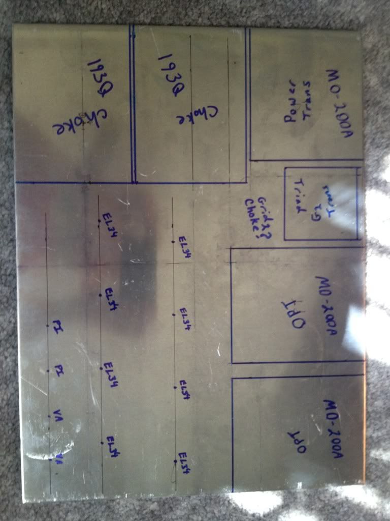
Thanks!
Blair
Thanks!
Blair
- Blair
- KT88
- Posts: 1272
- Joined: Thu Nov 09, 2006 10:22 am
![]() by kheper » Mon Sep 03, 2012 9:37 am
by kheper » Mon Sep 03, 2012 9:37 am
Blair wrote:Thanks Joe!
Now that I saw your post, I will be able to add quite tha amount of capacitance and choke.
Will this work as a grid choke to feed all 8 G2 screen grids?
http://item.mobileweb.ebay.com/viewitem ... 0460308248
It says 70mA, so I would think so.
Thanks!
Blair
Looking at the RCA handbook for El34 PP amps, they state ~10ma current draw per screen grid. Some datasheets are higher. 70ma is a little shy. I'd hold out for a 150ma choke.
-
kheper - KT88
- Posts: 1252
- Joined: Wed Dec 21, 2005 10:14 pm
- Location: Philly, PA


![]() by Blair » Sat Sep 08, 2012 9:09 am
by Blair » Sat Sep 08, 2012 9:09 am
I tested the output trannies last night, and using the color codes from the original MO-100 schematic, it looks like the primaries are 4.5K.
However, I ran test on each winding to do the math to see what my impedance would be into various loads, and I think I have a pretty decent plan.
The yellow winding into 4 ohms is around 2.9K
The Green into 8 ohms is around 2.3K
The Orange into 1 ohm is around 3.1K (Thinking about possibilities for ribbon speakers)
So, my personal speakers are 4 ohm nom. 3K is where I should aim because the green winding into 8 ohms is 2.3k so it would just run out of steam a little quicker right? At 3K it is really a 10 ohm winding.
What tubes in Pentode would work well into a 3K load? The Eal34 does look best from what I can see.
Also, assuming I may actually run the mono at some point, when you parallel the output transformers, it does not change the primary? (What the tubes see)?
I see there are no changes to the ST-70, etc. to run in mono.
Thanks!
Blair
- Blair
- KT88
- Posts: 1272
- Joined: Thu Nov 09, 2006 10:22 am
![]() by kheper » Mon Sep 10, 2012 11:31 am
by kheper » Mon Sep 10, 2012 11:31 am
Blair wrote:What tubes in Pentode would work well into a 3K load? The Eal34 does look best from what I can see.
Blair
Have you thought of 6L6GCs? They are 30W tubes, and some of the datasheets show that they like lowish primary input impedance ~3.5K in PP pentode mode. [I don't not think the primary impedance is all that important. You will be running in PPP pentode mode.]
http://www.nj7p.info/Common/Tube/SQL/Tu ... Type=6L6GC
http://tdsl.duncanamps.com/link.php?target=5525C52D
-
kheper - KT88
- Posts: 1252
- Joined: Wed Dec 21, 2005 10:14 pm
- Location: Philly, PA
![]() by Blair » Mon Sep 10, 2012 11:41 am
by Blair » Mon Sep 10, 2012 11:41 am
Hi Joe,
I did, but I'm not putting almost 700v on the plate of a 6l6.
I'm reconsidering a few things here. A) PPP, while it is nice, it will require twice the current as PP. The "correct" primary impedance of the output iron is 4.5K, so of I just wire it like it was designed with the output in parallel, I could run 6550 or KT88 in PP and it is a perfect Pentode load for them and the high b+ is similar to their datasheet yielding 100W at 3% using 300V on sg2.
Any thoughts on why that would be a bad idea? Then I could use a single choke as well.
Of course, then I need anothe MO-200, but hey....
Thanks!
Blair
- Blair
- KT88
- Posts: 1272
- Joined: Thu Nov 09, 2006 10:22 am
54 posts
• Page 3 of 4 • 1, 2, 3, 4
Who is online
Users browsing this forum: No registered users and 43 guests