http://makearadio.com/schematics/images ... 100a-2.jpg
Hi guys,
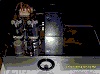
This old Bogen amp looks pretty nice from a specs perspective. I have seen them used as modded amps for hifi. How would you connect this amp to your speakers though? It is not a traditional output transformer because it has the high voltage distribution taps. I see the 25V tap labeled as 6ohms, so it should work on hifi speakers, but do you just connect from common to 25V?
Anyone ever use these output transformers?
Thanks!
Blair
Bogen MO-200A conversion
54 posts
• Page 1 of 4 • 1, 2, 3, 4
Bogen MO-200A conversion
![]() by Blair » Mon Aug 13, 2012 7:29 pm
by Blair » Mon Aug 13, 2012 7:29 pm
Last edited by Blair on Fri Aug 31, 2012 7:45 am, edited 1 time in total.
- Blair
- KT88
- Posts: 1272
- Joined: Thu Nov 09, 2006 10:22 am
![]() by Tubeamp » Mon Aug 13, 2012 9:14 pm
by Tubeamp » Mon Aug 13, 2012 9:14 pm
Hi Blair, how are you ?
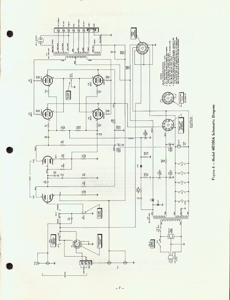
Have a look at this : http://www.bogen.com/support/discontinu ... O100Am.pdf
On page 3, see the "Output" paragraph, it describes connection details.
Have a nice time!
Have a look at this : http://www.bogen.com/support/discontinu ... O100Am.pdf
On page 3, see the "Output" paragraph, it describes connection details.
Have a nice time!
-
Tubeamp - Posts: 71
- Joined: Sun Jul 18, 2010 3:41 am
- Location: Cyprus
![]() by EWBrown » Tue Aug 14, 2012 6:57 pm
by EWBrown » Tue Aug 14, 2012 6:57 pm
With PA amps, it is the common practice to express the audio outputs in terms of voltage, rather than in units of secondary impedance "ohms",
this is applied to the audio output distribution into a group or quantity of remotely located PA speakers, which also must have have "line matching" transformers, to make them "play well" with the speakers.
Appling Ohm's law, for 100 watts output power, the equivalent output Z would be: V squared, divided by power;
For 25V distribution; (25 X 25 / 100) = 6.25 Ohms.
Similarly,
For 70V (actually 70.7) V distribution, (70.7 X 70.7 / 100) = 50 ohms.
49 ohms, 49.5 ohms, meh......
I worked on, and designed, PA systems at a previous job in the latter 1990s...
And I operate the sound system at the Church on Sundays, and maintain the somewhat antiquated system components, during the rest of the week .
 (even up to fixing broken wireless lapelmics and xmitters)
Neat trick, if you have a vintage Collins or other vintage tube or SS military / "spook" radio, which has a "600 ohm" audio output,
use a 25V line matching xfmr, and the 1 watt secondary connections. OK, it will actually be 625 ohms,
but then, that's more than "close enough" for government work
Generally, the speakers used in PA systems are 8 ohms, the matcher converts the line signal voltage to the speaker.
HTH
I hope that I didn't muddy the waters too much
/ed B
this is applied to the audio output distribution into a group or quantity of remotely located PA speakers, which also must have have "line matching" transformers, to make them "play well" with the speakers.
Appling Ohm's law, for 100 watts output power, the equivalent output Z would be: V squared, divided by power;
For 25V distribution; (25 X 25 / 100) = 6.25 Ohms.
Similarly,
For 70V (actually 70.7) V distribution, (70.7 X 70.7 / 100) = 50 ohms.
49 ohms, 49.5 ohms, meh......
I worked on, and designed, PA systems at a previous job in the latter 1990s...
And I operate the sound system at the Church on Sundays, and maintain the somewhat antiquated system components, during the rest of the week .
(even up to fixing broken wireless lapelmics and xmitters)
Neat trick, if you have a vintage Collins or other vintage tube or SS military / "spook" radio, which has a "600 ohm" audio output,
use a 25V line matching xfmr, and the 1 watt secondary connections. OK, it will actually be 625 ohms,
but then, that's more than "close enough" for government work
Generally, the speakers used in PA systems are 8 ohms, the matcher converts the line signal voltage to the speaker.
HTH
I hope that I didn't muddy the waters too much
/ed B
Real Radios Glow in the Dark
-

EWBrown - Insulator & Iron Magnate
- Posts: 6389
- Joined: Wed Mar 19, 2003 6:03 am
- Location: Now located in Clay County, NC !
![]() by Blair » Tue Aug 14, 2012 7:09 pm
by Blair » Tue Aug 14, 2012 7:09 pm
Hi Ed,
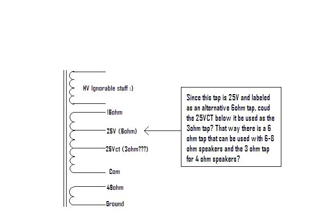
Not at all! Actually, I was looking at the MO-100 schematic and thinking that the 6 ohm tap could be used for 4-8 ohm speakers on the MO-100.
The thing that got me interested is the big brother to this amp which uses the exact same amp, but two in parallel. This yields an 8 ohm output and the 25v tap at 3 ohms. There is a center tap from the common to the 25v (3 ohm) tap.
Sometimes I get people asking about amps to drive ribbons which are inherently low impedance. If you used the CT and common from the 25v (3ohm) output to yield a 1.5 ohm output that will deliver into a 1.5ohm load?
Hope that makes sense?
Thanks,
Blair
- Blair
- KT88
- Posts: 1272
- Joined: Thu Nov 09, 2006 10:22 am
![]() by Blair » Thu Aug 16, 2012 6:27 am
by Blair » Thu Aug 16, 2012 6:27 am
OK,
I bought one of these, but a stereo version. Well, a mono to convert to stereo. The original driver circuit looks OK. Do you think it would be an upgrade to go with a different VA/PI arrangement?
There is an extra 9 pin socket if I chose something like the Poseidon front end.
I should probably add that this amp runs 650-680V on the plates. I have seen several threads where people have converted it for 6550 and EL34 power tubes. I will not know the P-P impedance of the output iron until I get the amp, so that may change things, but which tube will handle the high plate voltage the best? Or is KT88 the way to go? I am also considering building another chassis and adding a separate transformer for the grids to keep them solid at a fixed voltage. Good idea?
The reason for the Bogen is that I was very impressed with the last build I did using Bogen iron. It spec'd out within 5% of his stated claims from 18hz-45Khz, and the 5% or so was just the roll off at the top.
Thanks!
Blair
- Blair
- KT88
- Posts: 1272
- Joined: Thu Nov 09, 2006 10:22 am
![]() by Blair » Thu Aug 16, 2012 9:07 pm
by Blair » Thu Aug 16, 2012 9:07 pm
I'd like to try something different with this one.
A few questions for the gurus:
1) The design I bought is the MO-200. It uses two output transformers in parallel. Bogen claims excellent response despite the parallel output transformers. I have read on many st70 threads that this is a bad idea. I was thinking about putting a switch to go from stereo to mono. Is this a bad idea?
2) Will a LM317 work as a CCS for each pair of EL34s? After doing some research, it looks like the EL34 will handle the 660V better than the 6550.
3) I mentioned changing the front end, but is there anything really wrong with the original front end? There is an AudioKarma thread where one of these has been modded to a pentode driver and a 5670 PI, but I don't really see the benefit to this over any other topology like the Williamson, etc.
I'm also debating a complete transplant so I can add a choje to the PS and a separate grid supply. Is this worth it? I've seen claims that people have used this chassis and basic PS and get pretty low noise.
Lots of questions, but that's half the fun right:)
Thanks!
Blair
- Blair
- KT88
- Posts: 1272
- Joined: Thu Nov 09, 2006 10:22 am
![]() by EWBrown » Thu Aug 16, 2012 9:10 pm
by EWBrown » Thu Aug 16, 2012 9:10 pm
6 ohms would work well with either 4 or 8 ohm speakers, try either value, one may sound better than the other, as the secondary's load does get reflected back into the OPT's primary.
Bogen had a couple of hefty amps, one was mono, the other stereo, which used the PP 6AV5GAs with a B+ of over 650VDC, and for the G2 , regulated 160VDC, with simple reg circuit utilizing a 6CG7.
Like this one:

/ed B
Bogen had a couple of hefty amps, one was mono, the other stereo, which used the PP 6AV5GAs with a B+ of over 650VDC, and for the G2 , regulated 160VDC, with simple reg circuit utilizing a 6CG7.
Like this one:
/ed B
Last edited by EWBrown on Fri Aug 24, 2012 9:06 am, edited 2 times in total.
Real Radios Glow in the Dark
-
EWBrown - Insulator & Iron Magnate
- Posts: 6389
- Joined: Wed Mar 19, 2003 6:03 am
- Location: Now located in Clay County, NC !
![]() by Blair » Fri Aug 17, 2012 7:44 am
by Blair » Fri Aug 17, 2012 7:44 am
Looking at the original schematic, is there any reason to modify it? That is what most people do with these. I suppose I could add a 12AX7 as the VA and use a 12AU7 PI. The original circuit looks very minimalist and clean though. Does it look like there needs to be anything done to run EL34s in the schematic? I do plan to change it to individual bias.
Thanks!
Blair
Thanks!
Blair
- Blair
- KT88
- Posts: 1272
- Joined: Thu Nov 09, 2006 10:22 am
![]() by battradio » Fri Aug 17, 2012 1:25 pm
by battradio » Fri Aug 17, 2012 1:25 pm
If i remember corectly , the driver section will have to be changed to drive EL34's or 6550 , also make sure the bias has enough range 8417 don't need as much bias as EL34's
Mark

-

battradio - KT88
- Posts: 927
- Joined: Tue Mar 10, 2009 12:58 am
- Location: near ST.Louis MO.
![]() by Blair » Fri Aug 17, 2012 6:03 pm
by Blair » Fri Aug 17, 2012 6:03 pm
Hi Mark,
I plan to transplant this amp to a fresh chassis, so I can do what I want with it. I am going to add another transformer for the bias, and the grids. You think a traditional VA/PI stage would be better?
Thanks,
Blair
I plan to transplant this amp to a fresh chassis, so I can do what I want with it. I am going to add another transformer for the bias, and the grids. You think a traditional VA/PI stage would be better?
Thanks,
Blair
- Blair
- KT88
- Posts: 1272
- Joined: Thu Nov 09, 2006 10:22 am
![]() by battradio » Fri Aug 17, 2012 7:37 pm
by battradio » Fri Aug 17, 2012 7:37 pm
Blair wrote:Hi Mark,
I plan to transplant this amp to a fresh chassis, so I can do what I want with it. I am going to add another transformer for the bias, and the grids. You think a traditional VA/PI stage would be better?
Thanks,
Blair
yes an Eclone would be great with EL34's
Mark
-
battradio - KT88
- Posts: 927
- Joined: Tue Mar 10, 2009 12:58 am
- Location: near ST.Louis MO.
![]() by dcgillespie » Sat Aug 18, 2012 6:44 am
by dcgillespie » Sat Aug 18, 2012 6:44 am
If you consider the 25 volt tap a 6 ohm output, then the CT of this winding (i.e., a 12.5 volt tap) would represent a 1.5 ohm output to develop the same power output.
If the OPT can pass full power with low distortion down to 20 Hz, that is impressive indeed, as most PA type equipment falls apart at that frequency and power level.
Best to wait on determining an alternate output tube choice until you know what the output transformer represent in terms of a primary load. Either, way, changing to any different output tube will likely require that some help be given to the phase inverter, as 8417s could basically be driven by EL84 type driver circuits.
Dave
- dcgillespie
- KT88
- Posts: 399
- Joined: Sun Mar 08, 2009 5:34 am
- Location: Ball Ground, GA
54 posts
• Page 1 of 4 • 1, 2, 3, 4
Who is online
Users browsing this forum: No registered users and 47 guests