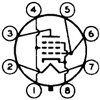
I recently bought an old monoblock chassis with working transformers on eBay for cheap and I need help identifying the OPT values. This is what I have so far:
- Identfied A1, A2, and HT on the primary. A1-A2 has approx. 190 ohms. A1-HT and A2-HT have approx. 100 ohms.
- Got N. With A1 and A2 connected to main, the secondary was 4.6VAC, so N=(120VAC/4.6VAC) squared = 680.
- I want to know the secondary impedance , so that I can calculate the primary impedance (680 x secondary impedance).
The secondary has only two wires. Can anybody suggest the way I can find out what its impedance is? I assume it's 8 ohms, but I want to make sure. Thanks,
-Min
Identifying unkown output transformers
7 posts
• Page 1 of 1
For practical purposes, the secondary is what you say it is--or, more precisely, what the speaker says it is. If you're planning to use an 8Ω speaker with it, base your calculations accordingly.
Just remember the First Rule of Transformers: It's all about ratios.
Just remember the First Rule of Transformers: It's all about ratios.
Eric in the Jefferson State
- erichayes
- KT88
- Posts: 987
- Joined: Fri Jan 23, 2004 9:01 pm
- Location: McKinleyville CA
8 is the number of ohms of your secondary windings
5500 ohms is a pretty common OPT P-P impedance, and 680 X 8 comes out pretty close enough to 5500, so I'd place a small wager that the secondary is 8 ohms!
Essentially, the primary will "reflect" the secondary's loading.
If it were 4 ohms, the primary would then have to be around 2.75K P-P, which is fairly uncommon, except for parallel push-pull, fairly high power situations.
HTH
/ed B in NH
Essentially, the primary will "reflect" the secondary's loading.
If it were 4 ohms, the primary would then have to be around 2.75K P-P, which is fairly uncommon, except for parallel push-pull, fairly high power situations.
HTH
/ed B in NH
Real Radios Glow in the Dark
-

EWBrown - Insulator & Iron Magnate
- Posts: 6389
- Joined: Wed Mar 19, 2003 6:03 am
- Location: Now located in Clay County, NC !
Cool! Now, can I use it for SE applications? I really want to make a stereo using these transformers, but I only have one OPT. Would it be feasible to use a OPT that have similar values, e.g. 5,500 ohms primary impedance for 8 ohms secondary? Thanks again.
-

SDS-PAGE - KT88
- Posts: 865
- Joined: Thu Feb 22, 2007 4:41 pm
- Location: Brandon, SD
most transformers designed for push-pull use won't work at all in SE. the current cancels out when phases are combined in a PP design but the constant flow of current in SE would quickly saturate this transformer. if you only have one, why not try a guitar amp? or maybe search eBay for a mate.
-

sorenj07 - KT88
- Posts: 925
- Joined: Tue May 02, 2006 2:39 pm
- Location: Berlin
The origin of the console that had these trannies is a complete mystery. No labels to be found anywhere, including trannies themselves. So, finding a mate will be impossible. Quit playing guitar a long ago. I do play the didgeridoo though.
So, what makes a tranny exclusively SE or PP? How would you test if your trans is for SE or PP? This will be good to know.
So, what makes a tranny exclusively SE or PP? How would you test if your trans is for SE or PP? This will be good to know.
-

SDS-PAGE - KT88
- Posts: 865
- Joined: Thu Feb 22, 2007 4:41 pm
- Location: Brandon, SD
Transformers for single ended use have a factory set air gap in the core to prevent the DC idle current from magnetically saturating the transformer core. The windings are also different from those in a push pull output transformer. In a PP OT the idle current flows in opposite directions through the windings. The two opposing magnetic fields cancel each other out so saturation is not an issue. However, if one tube in the PP pair carries significantly more current that the other then magnetic saturation can be an issue. *Which is why the recently suggested mismatched PP output tubes (Arnold/Jerry effect) wouldn't work*
To get around the saturation issue there are a class of SE circuits called Paraphase which route the tubes DC idle current through a separate choke and capacitively couple the AC through the output transformer essentially making two parallel circuits, one for the DC and one for that AC.
If your output is PP then there will be a pair or a quad of output tubes per tranny. SE circuits usually only use one tube.
-

mesherm - KT88
- Posts: 1232
- Joined: Fri Aug 27, 2004 10:33 pm
- Location: Alvin Texas
7 posts
• Page 1 of 1
Who is online
Users browsing this forum: No registered users and 45 guests
