I have a K12-M (monoblock) that I use at work for background music that has suddenly started shrieking and distorting on me (almost like feedback). I've tried different tubes and a different speaker and no dice. Could it be a feedback resistor? A coupling cap? Any ideas? Help!
-Derek
Help, my K12-M is shrieking at me!
13 posts
• Page 1 of 1
Help, my K12-M is shrieking at me!
![]() by DerekVa » Wed Jan 10, 2007 11:27 am
by DerekVa » Wed Jan 10, 2007 11:27 am
- DerekVa
- Posts: 226
- Joined: Sat Jun 10, 2006 12:43 am
- Location: Woodinville, WA
![]() by EWBrown » Wed Jan 10, 2007 2:16 pm
by EWBrown » Wed Jan 10, 2007 2:16 pm
I'll relay some advice from the Bottlehead site: first check the all of solder connections, one could be flaky, or corroded. Sometimes these can lay dormant for a long time, then "go off" like a land mine, totally unexpected. I've been soldering for about 45 years, and I still make a dull / blob solder job, once in a while.
The PC boards that are supplied woth the K-12 / K502 /S-5 aren't of the best quality...
/ed B in NH
The PC boards that are supplied woth the K-12 / K502 /S-5 aren't of the best quality...
/ed B in NH
Real Radios Glow in the Dark
-

EWBrown - Insulator & Iron Magnate
- Posts: 6389
- Joined: Wed Mar 19, 2003 6:03 am
- Location: Now located in Clay County, NC !
![]() by EWBrown » Thu Jan 11, 2007 6:32 am
by EWBrown » Thu Jan 11, 2007 6:32 am
I do have an original K-12 (stereo) schematic on this system, which I had siphoned off the net way back long time ago,I could e-mail it or attempt to post it here. I also had more recently scanned in the schematic with all my mods, but can't locate where it is "hiding" on which one of four computers... The cyber-landfill seems to get more and more full every day... :o
/ed B in NH
/ed B in NH
Last edited by EWBrown on Thu Jan 11, 2007 7:00 am, edited 1 time in total.
Real Radios Glow in the Dark
-
EWBrown - Insulator & Iron Magnate
- Posts: 6389
- Joined: Wed Mar 19, 2003 6:03 am
- Location: Now located in Clay County, NC !
![]() by Shannon Parks » Thu Jan 11, 2007 6:37 am
by Shannon Parks » Thu Jan 11, 2007 6:37 am
Does it happen one only one channel? Is the circuit modded at all?
- designer of fine tube audio gear at (((parks audio)))
- founder and admin of the diytube forums
-

Shannon Parks - Site Admin
- Posts: 3764
- Joined: Tue Mar 18, 2003 5:40 pm
- Location: Poulsbo, Washington
![]() by mesherm » Thu Jan 11, 2007 7:16 am
by mesherm » Thu Jan 11, 2007 7:16 am
Here is the schematic for the stereo 11MS8 version.
http://webpages.charter.net/mesherm/k12m_schematic.jpg
http://webpages.charter.net/mesherm/k12m_schematic.jpg
-

mesherm - KT88
- Posts: 1232
- Joined: Fri Aug 27, 2004 10:33 pm
- Location: Alvin Texas
All the basic mods, in one location!
![]() by EWBrown » Thu Jan 11, 2007 8:10 am
by EWBrown » Thu Jan 11, 2007 8:10 am
The circuit for the monoblock version is exactly the same, except one channel only.
11MS8s can be replaced directly with 10GV8s, plug 'n' play, no mods required!
If you build the amp on the pine board, it will be hummy and buzzy, this can be reduced by wiring all the trannie frames together, then connecting to the ground trace next to one of the input jacks. My reccomendation, keep the wood for another crafts project, and use a metal plate or chassis.
If you use a chassis, mount all the components, except for the smaller resistors and diode bridge, on the etch side of the board. The smaller resistors can be mounted on the socket side. If you have the plastic sockets and O-rings, toss 'em and use the same-sized ceramic sockets (available at Triode, etc). Newer kits won't have the plasticrap ones)
And ditch the lamp cord switch, it is really "bush league", use a normal chassis mounted power switch, and fuse holder. (and a good time to connect a CL90 in series with the switch/fuse side of the primary circuit, see below).
I'll recap the basic mods:
Before anything else: connect a CL90 inrush current limiter (same as used on the DIY35) on the primary of the power trannie. This will make life a LOT easier for the tubes' filaments, and other PSU components.
If you use a metal chassis, ditch the crummy little board-mounted pot and use one of the Radio Shark 100K "Alps" pots for about $3, they're a bargain! Watch the pot wiring, it's easy to mess up Yellow_Light_Colorz_PDT_09
1: Replace all the 0.22 uF coupling caps with WIMA 0,15 uF "red brick" MKP caps - they fit the PCB holes perfectly!
2: Bypass the 300 ohm, 3W cathode resistors with 100 to 470 uF / 35V eiectrolytics. Improves LF response
3: Connect a 470 uF / 350-450 VDC electrolytic directly across the 220 uF PSU cap (don't jumper to any other part of the ground trace, this will create a huge hummmm ground loop situation). Gives better LF and transient response.
4: Connect a 2 - 4 uF MKP cap directly across the 100 uF PSU cap (this lowers ESR, and improves HF response).
5: Replace the BR1 bridge with four uF4007 rectifiers - this takes a bit of creativity to do. Reduces 120HZ buzz.
6: The OPTs can be replaces with Hammond 1609s, they closely match the primary impedance of the original UTK brand OPTs) 1608s will also work just fine.
Note: 11MS8s and 10GV8s aren't as UL-friendly as 11BM8s or 16A8s, try it if you want, but the results are rather disappointing.
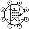
For 11BM8s / 16A8s (note, the tubes have a different pinout) , cut the traces to the screen grid for each pentode section, then connect to the appropriate UL tap on the 1609s (1608s will also work, but 10K is a better match for the tubes.
I found that these amps will still have a residual 60HZ AC hum, that seems to be incurable. THis is caused by the poor PCB layout, the filament power traces cun between the pins of the four interstage coupling caps. This injects a little Ac signal right onto the pentode's input grids.
Two solutions, neither is really simple.
1: Cut the etches leading to all pins 4 and 5, on each tube. connect one end of a twisted pair to each tube's pins 4 and 5, and then connect the other end of the TPs directly to the filament trannie (this can be done where they connect to the PCB, or use a terminal strip.
2: DC filament voltage, though this will require a separate filament trannie, rectifiers and electrolytic cap, or use a 12VDC, 3A brick.
The power trannie's filament winding will melt down if you try rectifing and filtering it, the current rating isn't sufficient for this.
Best yet, combine the two methods!
3: Really going out on a limb: 11BM8s can be replaced with 16A8s, this requires a separate 16VAC, 2A (or greater) power trannie)
Similarly, 11MS8s (and 10GV8s) can be replaced with 6GV8, 9GV8, and any other available filament voltages). Also requires a separate filament trannie of the appropriate voltage.
What I did in my 11BM8 amp, was to add a 16VAC "junk box" filament trannie under the chassis, and then wire in a DPDT slide switch (mounted under the chassis) so that either 11BM8s or 16A8s could be used.
I like 16A8s better, because they are more easily available and dirt cheap for NOS.
6BM8s could be used, I didn't bother, just because they have a "premium" price...
50BM8s? Can be done, (use a 48VAC trannie, don't play with direct AC line power) :o Yellow_Light_Colorz_PDT_09 I haven't tried this, so you can be a "pioneer" if you dare Yellow_Light_Colorz_PDT_08
/ed B in NH
11MS8s can be replaced directly with 10GV8s, plug 'n' play, no mods required!
If you build the amp on the pine board, it will be hummy and buzzy, this can be reduced by wiring all the trannie frames together, then connecting to the ground trace next to one of the input jacks. My reccomendation, keep the wood for another crafts project, and use a metal plate or chassis.
If you use a chassis, mount all the components, except for the smaller resistors and diode bridge, on the etch side of the board. The smaller resistors can be mounted on the socket side. If you have the plastic sockets and O-rings, toss 'em and use the same-sized ceramic sockets (available at Triode, etc). Newer kits won't have the plasticrap ones)
And ditch the lamp cord switch, it is really "bush league", use a normal chassis mounted power switch, and fuse holder. (and a good time to connect a CL90 in series with the switch/fuse side of the primary circuit, see below).
I'll recap the basic mods:
Before anything else: connect a CL90 inrush current limiter (same as used on the DIY35) on the primary of the power trannie. This will make life a LOT easier for the tubes' filaments, and other PSU components.
If you use a metal chassis, ditch the crummy little board-mounted pot and use one of the Radio Shark 100K "Alps" pots for about $3, they're a bargain! Watch the pot wiring, it's easy to mess up Yellow_Light_Colorz_PDT_09
1: Replace all the 0.22 uF coupling caps with WIMA 0,15 uF "red brick" MKP caps - they fit the PCB holes perfectly!
2: Bypass the 300 ohm, 3W cathode resistors with 100 to 470 uF / 35V eiectrolytics. Improves LF response
3: Connect a 470 uF / 350-450 VDC electrolytic directly across the 220 uF PSU cap (don't jumper to any other part of the ground trace, this will create a huge hummmm ground loop situation). Gives better LF and transient response.
4: Connect a 2 - 4 uF MKP cap directly across the 100 uF PSU cap (this lowers ESR, and improves HF response).
5: Replace the BR1 bridge with four uF4007 rectifiers - this takes a bit of creativity to do. Reduces 120HZ buzz.
6: The OPTs can be replaces with Hammond 1609s, they closely match the primary impedance of the original UTK brand OPTs) 1608s will also work just fine.
Note: 11MS8s and 10GV8s aren't as UL-friendly as 11BM8s or 16A8s, try it if you want, but the results are rather disappointing.
For 11BM8s / 16A8s (note, the tubes have a different pinout) , cut the traces to the screen grid for each pentode section, then connect to the appropriate UL tap on the 1609s (1608s will also work, but 10K is a better match for the tubes.
I found that these amps will still have a residual 60HZ AC hum, that seems to be incurable. THis is caused by the poor PCB layout, the filament power traces cun between the pins of the four interstage coupling caps. This injects a little Ac signal right onto the pentode's input grids.
Two solutions, neither is really simple.
1: Cut the etches leading to all pins 4 and 5, on each tube. connect one end of a twisted pair to each tube's pins 4 and 5, and then connect the other end of the TPs directly to the filament trannie (this can be done where they connect to the PCB, or use a terminal strip.
2: DC filament voltage, though this will require a separate filament trannie, rectifiers and electrolytic cap, or use a 12VDC, 3A brick.
The power trannie's filament winding will melt down if you try rectifing and filtering it, the current rating isn't sufficient for this.
Best yet, combine the two methods!
3: Really going out on a limb: 11BM8s can be replaced with 16A8s, this requires a separate 16VAC, 2A (or greater) power trannie)
Similarly, 11MS8s (and 10GV8s) can be replaced with 6GV8, 9GV8, and any other available filament voltages). Also requires a separate filament trannie of the appropriate voltage.
What I did in my 11BM8 amp, was to add a 16VAC "junk box" filament trannie under the chassis, and then wire in a DPDT slide switch (mounted under the chassis) so that either 11BM8s or 16A8s could be used.
I like 16A8s better, because they are more easily available and dirt cheap for NOS.
6BM8s could be used, I didn't bother, just because they have a "premium" price...
50BM8s? Can be done, (use a 48VAC trannie, don't play with direct AC line power) :o Yellow_Light_Colorz_PDT_09 I haven't tried this, so you can be a "pioneer" if you dare Yellow_Light_Colorz_PDT_08
/ed B in NH
Real Radios Glow in the Dark
-
EWBrown - Insulator & Iron Magnate
- Posts: 6389
- Joined: Wed Mar 19, 2003 6:03 am
- Location: Now located in Clay County, NC !
![]() by Brik » Thu Jan 11, 2007 4:30 pm
by Brik » Thu Jan 11, 2007 4:30 pm
Great post. I followed most of Ed's suggestions and ended up with a great sounding amp.
The Ultra Linear connections on the 10GV8 made the amp sound like the speakers are made of tin cans. Inserting 820ohm resistors between the transformer's UL tap and the 10GV8's grid2 made the UL connection work much better. Kinda like the circuit below:
/BriK
The Ultra Linear connections on the 10GV8 made the amp sound like the speakers are made of tin cans. Inserting 820ohm resistors between the transformer's UL tap and the 10GV8's grid2 made the UL connection work much better. Kinda like the circuit below:
/BriK
-

Brik - Posts: 204
- Joined: Fri Apr 07, 2006 5:30 pm
- Location: West of Boston
![]() by EWBrown » Fri Jan 12, 2007 7:11 am
by EWBrown » Fri Jan 12, 2007 7:11 am
I hadn't thought of trying SG resistors in the 11MS8 UL hookup. The original UL result was less than stellar, and "tin cans" sound is an apt description. Yellow_Light_Colorz_PDT_06
I built these as the K-12M monoblocks, with the Hammond UL trannies, onto some Hammond 10X6X2 steel chassis, and I copied a trick from VTL and added in a pentode / UL switch (definitely not to be "hot switched"). I still have to add volume pots to these, I'll add in the 820R resistors at the same time, thanks! I had thought of labeling the SG switches as "hifi" and "Victrola" (sound quality). Yellow_Light_Colorz_PDT_08
The early 11BM8 version of the stereo amp not only had thpse lousy melt-a-matic plastic tube sockets, but the supplied schematic still showed the 11MS8 pinouts. It didn't affect the assembly procedures, but it made initial voltage and resistance measurements very confusing... Yellow_Light_Colorz_PDT_09
/ed B in NH
Real Radios Glow in the Dark
-
EWBrown - Insulator & Iron Magnate
- Posts: 6389
- Joined: Wed Mar 19, 2003 6:03 am
- Location: Now located in Clay County, NC !
AHA!!!
![]() by DerekVa » Mon Jan 15, 2007 11:51 pm
by DerekVa » Mon Jan 15, 2007 11:51 pm
Figured it out. The negative speaker post / output transformer (-) had dropped its ground and wasn't tied to the chassis / the remainder of the circuit (I'm going with a ground bus out of 12GA copper that ties to the negative speaker post which is also tied to the OPT). Evidently, as Ed so accurately predicted, it was a bad solder joint.
Of course, it was the last thing I checked. Yellow_Light_Colorz_PDT_08
-Derek
Of course, it was the last thing I checked. Yellow_Light_Colorz_PDT_08
-Derek
- DerekVa
- Posts: 226
- Joined: Sat Jun 10, 2006 12:43 am
- Location: Woodinville, WA
![]() by EWBrown » Wed Jan 17, 2007 6:50 am
by EWBrown » Wed Jan 17, 2007 6:50 am
I added the volume pots and the 820 ohm SG resistors on my 11MS8 K501 (K12M) monoblox this weekend, the sound has definitely improved, but there is a significant power output drop on the UL mode. I'll have to dig up some 10GV8s and try them out.
The sound source was an ancient Japanese tube mono FM tuner that I got at a local antique / junk shop for cheap. I think it's made by TRIO, which is the forerunner of KEnwood. It covers 76 to 108 MC (not MHz) snf works very well, and was well cared-for by its previous owner(s). The test speaker was a flea-market foundling JBL MR26. I wish I could find another one for $5 too,, that would be nice Yellow_Light_Colorz_PDT_02
BTW, another 11BM8 alternative is 8B8, same characteristics, 8V filament voltage. These are usually dirt cheap, as well as 16A8s.
/ed B in the glacier fields of frozen NH
Real Radios Glow in the Dark
-
EWBrown - Insulator & Iron Magnate
- Posts: 6389
- Joined: Wed Mar 19, 2003 6:03 am
- Location: Now located in Clay County, NC !
![]() by EWBrown » Wed Jan 17, 2007 2:13 pm
by EWBrown » Wed Jan 17, 2007 2:13 pm
Two more *BM8 alternatives: 6HC8 (fat bottle 6BM8, higher pentode plate dissipation, and 17HC8, good 16A8 alternative:
http://www.shinjo.info/frank/sheets/106/6/6HC8.pdf
These may be somewhathard to find, AES has none of either available.
Probably considered TV "plinkers", especially the 17HC8s.
/ed B in "iceland"
http://www.shinjo.info/frank/sheets/106/6/6HC8.pdf
These may be somewhathard to find, AES has none of either available.
Probably considered TV "plinkers", especially the 17HC8s.
/ed B in "iceland"
Real Radios Glow in the Dark
-
EWBrown - Insulator & Iron Magnate
- Posts: 6389
- Joined: Wed Mar 19, 2003 6:03 am
- Location: Now located in Clay County, NC !
How I modified my K12M (mono)
![]() by DerekVa » Thu Jan 18, 2007 11:41 pm
by DerekVa » Thu Jan 18, 2007 11:41 pm
1) Ceramic tube sockets (hmmm...these don't melt!)
2) PSU capacitor - replaced the existing PSU caps with a dual-section 220mf / 350V Elna Cerefine
3) Volume Pot - Radio Shack 100k to replace the craptastic stock pot
4) Chassis - 10x6x2 Hammond box - better than pine
5) 6-position rotary switch for multiple inputs
6) IEC power cord instead of lamp cord
7) 12GA copper ground bus to a single-point on the chassis
I haven't tried the Wimas nor the heater modification (both DC modification as well as cutting the traces), although these would be fairly simple to implement.
Here's the amp now:

-Derek
2) PSU capacitor - replaced the existing PSU caps with a dual-section 220mf / 350V Elna Cerefine
3) Volume Pot - Radio Shack 100k to replace the craptastic stock pot
4) Chassis - 10x6x2 Hammond box - better than pine
5) 6-position rotary switch for multiple inputs
6) IEC power cord instead of lamp cord
7) 12GA copper ground bus to a single-point on the chassis
I haven't tried the Wimas nor the heater modification (both DC modification as well as cutting the traces), although these would be fairly simple to implement.
Here's the amp now:
-Derek
- DerekVa
- Posts: 226
- Joined: Sat Jun 10, 2006 12:43 am
- Location: Woodinville, WA
13 posts
• Page 1 of 1
Who is online
Users browsing this forum: No registered users and 46 guests