New Year's 6AV5GA SET project
No better way to kick off a new year! 
Quick before someone pipes up and says ,
,
I have real live pictures


The basic circuit of the amplifier is similar to SorenJ's 6AV5GA amp from a couple years ago - I'll append his schematic here:

There are some minor circuit changes, I used 270K for the grid resistors, 1K grid stoppers, 470 ohms, 1W for the 6AV5GA screen grid to plate connection, and 0.22 uF interstage couplers, and there is no input volume control. The OPTs are 3K primary impedance, 10W rating (Transcendars from an e-bay purchase of secveral years past).
The drivers use 12AT7s instead of 5965s, and the 6AV5 GA plate voltage is about 30-40VDC higher, and the RK is 750 ohms, 25W Dale "heatsink" resistors, mounted on the chassis, and using some silicon heatsink "grease". The power supply is a bit simpler than was Soren's, with basic CLCRC filtering.
Rather than compose a whole new write-up, I just copied and editied my posting of a week ago under the "my low watts amps" topic. Why re-invent the wheel,

So this contains a commentary of my original 6AV5GA- modified GSG project, and its evolutionary stages, which all served as a test bed for this amp.
I decided to stay with 6AV5GAs, damn the torpedoes, ful speed ahead
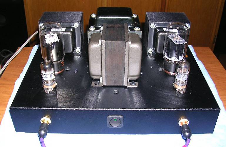
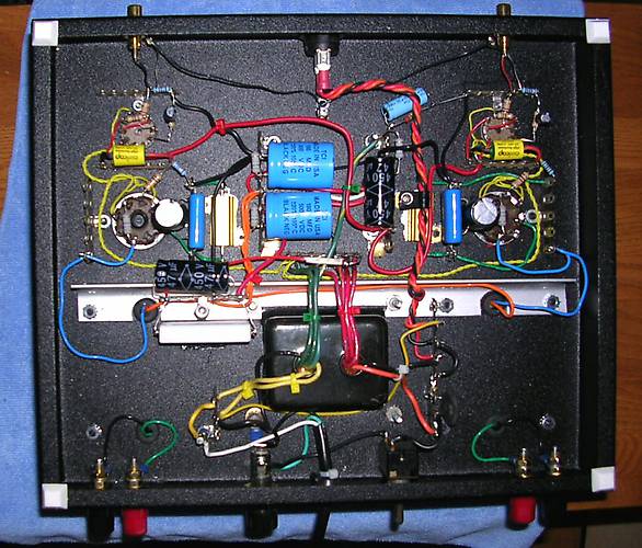
The Chassis is the "standard" Hammond steel, black powder-coated, 12 X 10 X 2 inch, which is one of my favorites. There is plenty of room under the hood for neat, clean and uncrowded point to point wiring.
I wired up the Power supply and output stages, using the Transcendar 10W, 3K SE OPTs, and 750 ohm 25W "heatsink" type dale cathode resistors.
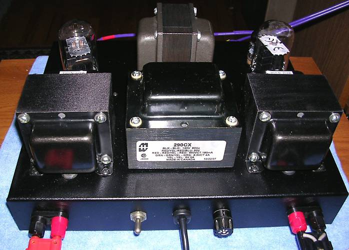
Power trannie is a horizontal-mount Hammond 290CX, and a 5H, 200 mA choke of unknown parentage, which I've had in the parts collection for several years. Caps are two 180 uF / 500V, and two 47 uF / 450V, rectifiers are the usual UF4007s, and I used a CL90 inrush current limiter on the AC primary side.
I used the 5VAC filament winding to "buck" the 115VAC rated primary voltage, in order to have more "appropriate" B+ and filament voltages.
This is all in the wiring located just to the left of the fuse holder. The thinner long yellow wire serves as the return for the front switch's internal green neon pilot light.
Yeah, you're not seeing double - there are two AC power switches, one on the rear, and a fancy illuminated one up front, which was a last-minute consideration. I was originally going to mount a 20 mm dia pilot light on the front, and then I found a nice illuminated power switch, so I used that, instead. The two AC power switches are connected in series.
I generally avoid using horizontal mount iron, as the nibbler tool "workout" is a real wrist-buster, but I do like the end results, I may go with this method more often (as I have a quantity of vintage, used and new horiz mount power and output trannies.
With 400V B+, the test 6AV5GAs were dissipating about 25 Watts combined plate and G2. Even though these tubes can take a lickin' and keep on tickin' I decided to throttle things back a bit, added an extra C (47 uF / 450V) and R (333 ohms, 30W, three 1K, 10W WW resistors in parallel), before the choke.. These are "hiding" behind the aluminum angle bracket.
That dropped the B+ to 365VDC, before the choke, and 350VDC to the OPT B+ connections.. Instead of 75 to 80 mA plate current, I now get 66 - 68 mA, and a V P-K of about 280V so I'm down to around 18-19W PD, which is closer to reality. Before I throtled it back, I ran tests on about three dozen 6AV5GAs and culled out the four weakest ones, and one which oscillated uncontrollably.
I even subjected half a dozen 6AV5GTs to this treatment, and they didn't blow up.either. I have some 6AU5s, but I figured they would detonate in short order, they kinda whimpy, in comparison...
I made up another SS 6AX5GT replacement, this time with 50 ohms in series with each uF4007 ,and I added another diode, LED and 680 ohm resistor across 2 and 7 to get a red "filament glow". I tried that out in the "blue plate special" GSG and get the same B+ voltages, though with a slightly lower cathode current, because of its approx 800 ohm vs. 750 ohm RK's.
With this combination, it is noticeably more powerful, better bass, and clear highs, I have run it this way for a few hours, with no ill effects on the tubes, and the PA774 just gets slightly warm. It now has 1.2A less loading on one of the two filament windings, so that saves about 7.5 VA's in the process. It definitely has a much better "Ka-Whump" factor, now 
Driver stages are SRPP 12AT7s, running around 3.3 mA, with RK+ RA = 470 ohms. and about 305VDC "top" plate voltage.
With all of the heavy iron on the top surface, I decided that it needed some under-the chassis bracing, so I worked up a piece of one-inch aluminum angle bracket to stiffen the chassis top, and to serve as the front mounting points for the power and output trannies. It did take a bit of creative cutting and trimmingh to fit.
The yellow 6.3VAC filament wiring is pre-twisted pair 22 ga teflon insulated (I have a big roll of this stuff) this may seem a light gauge wire for this purpose, but it also serves to trim off a couple of tenths of excess voltage from the 6.5VAC from the power trannie.
FWIW, the 290CX, which was intended as a guitar amp replacement transformer, is just about perfect for an ST-35 build, the voltages and currents are right, and it also has a 5VAC filament winding for those who like to use tube rectification - a 5AR4/GZ34 would be the best choice, and the tube rectifier voltage drop would deliver the correct ST35 B+ voltage..
/ed B in NC
Quick before someone pipes up and says
,I have real live pictures
The basic circuit of the amplifier is similar to SorenJ's 6AV5GA amp from a couple years ago - I'll append his schematic here:
There are some minor circuit changes, I used 270K for the grid resistors, 1K grid stoppers, 470 ohms, 1W for the 6AV5GA screen grid to plate connection, and 0.22 uF interstage couplers, and there is no input volume control. The OPTs are 3K primary impedance, 10W rating (Transcendars from an e-bay purchase of secveral years past).
The drivers use 12AT7s instead of 5965s, and the 6AV5 GA plate voltage is about 30-40VDC higher, and the RK is 750 ohms, 25W Dale "heatsink" resistors, mounted on the chassis, and using some silicon heatsink "grease". The power supply is a bit simpler than was Soren's, with basic CLCRC filtering.
Rather than compose a whole new write-up, I just copied and editied my posting of a week ago under the "my low watts amps" topic. Why re-invent the wheel,
So this contains a commentary of my original 6AV5GA- modified GSG project, and its evolutionary stages, which all served as a test bed for this amp.
I decided to stay with 6AV5GAs, damn the torpedoes, ful speed ahead
The Chassis is the "standard" Hammond steel, black powder-coated, 12 X 10 X 2 inch, which is one of my favorites. There is plenty of room under the hood for neat, clean and uncrowded point to point wiring.
I wired up the Power supply and output stages, using the Transcendar 10W, 3K SE OPTs, and 750 ohm 25W "heatsink" type dale cathode resistors.
Power trannie is a horizontal-mount Hammond 290CX, and a 5H, 200 mA choke of unknown parentage, which I've had in the parts collection for several years. Caps are two 180 uF / 500V, and two 47 uF / 450V, rectifiers are the usual UF4007s, and I used a CL90 inrush current limiter on the AC primary side.
I used the 5VAC filament winding to "buck" the 115VAC rated primary voltage, in order to have more "appropriate" B+ and filament voltages.
This is all in the wiring located just to the left of the fuse holder. The thinner long yellow wire serves as the return for the front switch's internal green neon pilot light.
Yeah, you're not seeing double - there are two AC power switches, one on the rear, and a fancy illuminated one up front, which was a last-minute consideration. I was originally going to mount a 20 mm dia pilot light on the front, and then I found a nice illuminated power switch, so I used that, instead. The two AC power switches are connected in series.
I generally avoid using horizontal mount iron, as the nibbler tool "workout" is a real wrist-buster, but I do like the end results, I may go with this method more often (as I have a quantity of vintage, used and new horiz mount power and output trannies.
With 400V B+, the test 6AV5GAs were dissipating about 25 Watts combined plate and G2. Even though these tubes can take a lickin' and keep on tickin' I decided to throttle things back a bit, added an extra C (47 uF / 450V) and R (333 ohms, 30W, three 1K, 10W WW resistors in parallel), before the choke.. These are "hiding" behind the aluminum angle bracket.
That dropped the B+ to 365VDC, before the choke, and 350VDC to the OPT B+ connections.. Instead of 75 to 80 mA plate current, I now get 66 - 68 mA, and a V P-K of about 280V so I'm down to around 18-19W PD, which is closer to reality. Before I throtled it back, I ran tests on about three dozen 6AV5GAs and culled out the four weakest ones, and one which oscillated uncontrollably.
I even subjected half a dozen 6AV5GTs to this treatment, and they didn't blow up.either. I have some 6AU5s, but I figured they would detonate in short order, they kinda whimpy, in comparison...
I made up another SS 6AX5GT replacement, this time with 50 ohms in series with each uF4007 ,and I added another diode, LED and 680 ohm resistor across 2 and 7 to get a red "filament glow". I tried that out in the "blue plate special" GSG and get the same B+ voltages, though with a slightly lower cathode current, because of its approx 800 ohm vs. 750 ohm RK's.
With this combination, it is noticeably more powerful, better bass, and clear highs, I have run it this way for a few hours, with no ill effects on the tubes, and the PA774 just gets slightly warm. It now has 1.2A less loading on one of the two filament windings, so that saves about 7.5 VA's in the process. It definitely has a much better "Ka-Whump" factor, now
Driver stages are SRPP 12AT7s, running around 3.3 mA, with RK+ RA = 470 ohms. and about 305VDC "top" plate voltage.
With all of the heavy iron on the top surface, I decided that it needed some under-the chassis bracing, so I worked up a piece of one-inch aluminum angle bracket to stiffen the chassis top, and to serve as the front mounting points for the power and output trannies. It did take a bit of creative cutting and trimmingh to fit.
The yellow 6.3VAC filament wiring is pre-twisted pair 22 ga teflon insulated (I have a big roll of this stuff) this may seem a light gauge wire for this purpose, but it also serves to trim off a couple of tenths of excess voltage from the 6.5VAC from the power trannie.
FWIW, the 290CX, which was intended as a guitar amp replacement transformer, is just about perfect for an ST-35 build, the voltages and currents are right, and it also has a 5VAC filament winding for those who like to use tube rectification - a 5AR4/GZ34 would be the best choice, and the tube rectifier voltage drop would deliver the correct ST35 B+ voltage..
/ed B in NC

 , usually just before they shatter and turn into malodorous schrapnel