http://picasaweb.google.bg/azazello52/K ... 0358965618
My tube preamplifier - lampizator for every transistor end stage in box of DVD - Sony.
PCC88 - Тесла & kenotron 6Ц4П
My low watts projects
![]() by EWBrown » Fri Oct 15, 2010 5:55 pm
by EWBrown » Fri Oct 15, 2010 5:55 pm
PCC88 - Тесла & kenotron 6Ц4П
Is that Tesla PCC88 and a rectifier ? I had to look up "Kenotron", it is a classic early tube era term for a rectifier tube, and the term "pliotron" was applied to any amplifier tube (with one or more grids). Magnetrons and Carcinortons arrived on the scene much later

The 6Ц4П kenotron appears to be very similar to a 6X4 rectifier.
I finished the 6Ф3П (6BM8) PSE-UL design today. Basically similar to the small 6BM8 / 6Ф3П design, but with paralleled output stages, and for the VA stage, I used 100K plate and 1K cathode resistors (and the other triode for each channel is unemployed at present. I had considerd SRPP for this, but decided to stay witn the standard grounded cathode VA design for now. THis resistor combination runs the stage around 1.14 mA which was my target, as I wanted a bit more "oomph" for driving two paralleled pentodes. "oomph, yuh, I know, real "techie" terminology there


OPTs are Edcor GXSE15-8-3.5K which works very nicely with paralleled output pentodes., in UL mode.
For the power trannie, I used a (no longer available) Musical Power Supplies PT-190 which has 190-0-190 rated at 220 mA DC, and two 6.3V, 2A filament windings. CLCRC filtering, 180 uF / 450V into C354 choke, into another 180/450, 3900 ohms, 3W, and a third 180/450 cap.
This gives me 230 VDC B+, and 225V on the plates, and 228V on the G2s. Cathode resistors are 390 ohms, 2W, bypassed with 330 uF / 50V.
I'm running the cathode curernt a bit "hotter" with this design, about 38-40 mA per pentode. If it proves to be too "hot" for the tube's well-being, the PT190 has a tapped primary, so I can lower the B+ voltage (as well as the current) by 5 or even 10% if it becomes necessary.
I also used the "RH84" plate feedback technique, 470K between pins 9 and 6 on one of the 6F3Ps (the one which also has the VA stage, naturally)
for each channel. The "magic formula" for this is R FB equals about 4.5 to 5 times the VA stage plate resistor value. in this case, 4.7X falls right in the middle
It's all built onto yet another odd-ball "dumpster" chassis I salvaged from work several years ago.
Once again, it sounds very good, and after a few hours' break-in period it sounds even better. Definitely has more "ballz" both in power and in LF response than the single 6Ф3П and TF103 SE combination.
Photos of this new amp and the small 6Ф3П amp will be forthcoming, just be patient
/ed B
Last edited by EWBrown on Wed May 08, 2013 7:28 pm, edited 2 times in total.
Real Radios Glow in the Dark
-

EWBrown - Insulator & Iron Magnate
- Posts: 6389
- Joined: Wed Mar 19, 2003 6:03 am
- Location: Now located in Clay County, NC !
![]() by Ty_Bower » Sat Oct 16, 2010 6:45 am
by Ty_Bower » Sat Oct 16, 2010 6:45 am
EWBrown wrote:oomph, yuh, I know, real "techie" terminology there
Is that anything like the "Woo Wu Factor" that Mike puts into every MQ grid choke?
"It's a different experience; the noise occlusion, crisp, clear sound, and defined powerful bass. Strong bass does not corrupt the higher frequencies, giving a very different overall feel of the sound, one that is, in my opinion, quite unique."
-

Ty_Bower - KT88
- Posts: 1494
- Joined: Wed Mar 21, 2007 2:50 pm
- Location: Newark, DE
WOO WU FACTOR
![]() by EWBrown » Sat Oct 16, 2010 3:37 pm
by EWBrown » Sat Oct 16, 2010 3:37 pm
Not to be confused with Homer Simpson's "Woo Hoo" factor 
/ed B
/ed B
Real Radios Glow in the Dark
-
EWBrown - Insulator & Iron Magnate
- Posts: 6389
- Joined: Wed Mar 19, 2003 6:03 am
- Location: Now located in Clay County, NC !
![]() by Ty_Bower » Sat Oct 16, 2010 5:40 pm
by Ty_Bower » Sat Oct 16, 2010 5:40 pm
EWBrown wrote:The latest completed project is a small 6BM8...
OK... I've got just about all the chassis work on mine done. All I have to do is figure out how to finish the wiring underneath. Any hints from the expert point-to-point builders?


"It's a different experience; the noise occlusion, crisp, clear sound, and defined powerful bass. Strong bass does not corrupt the higher frequencies, giving a very different overall feel of the sound, one that is, in my opinion, quite unique."
-
Ty_Bower - KT88
- Posts: 1494
- Joined: Wed Mar 21, 2007 2:50 pm
- Location: Newark, DE
![]() by EWBrown » Sat Oct 16, 2010 6:45 pm
by EWBrown » Sat Oct 16, 2010 6:45 pm
Put a 7-place terminal strip at each screw on each 6BM8 socket, this will give you 12 tie points (the grounded centers aren't used) to support all teh required tube support components. A few more terminal strips for the power supply components, between 4 to 6 of the five-plate terminal strips would be good. Just do a "dry run" layout with all the components, then once you have the positioning figured out, then drill and mount as needed. Best to do a few "paper trial runs" before committing it to metal.
You're right, those Ten-Pounder $20 Schumacher power trannie are huge monsters

 Those trannies could easily power 8 6BM8s and maybe even 12 Your 6BM8 amp is the "Goliath" when compared to my tiny "David" version, which I can easily hold in one hand. (see it further down the page, along with a compact 12B4A "Darlikg Killer"
I really like your nice wood bases and the nicely finished chassis plates .
.
You're right, those Ten-Pounder $20 Schumacher power trannie are huge monsters
Those trannies could easily power 8 6BM8s and maybe even 12 Your 6BM8 amp is the "Goliath" when compared to my tiny "David" version, which I can easily hold in one hand. (see it further down the page, along with a compact 12B4A "Darlikg Killer"
I really like your nice wood bases and the nicely finished chassis plates
.Last edited by EWBrown on Fri Nov 19, 2010 7:34 pm, edited 1 time in total.
Real Radios Glow in the Dark
-
EWBrown - Insulator & Iron Magnate
- Posts: 6389
- Joined: Wed Mar 19, 2003 6:03 am
- Location: Now located in Clay County, NC !
![]() by Ty_Bower » Sun Oct 17, 2010 7:56 am
by Ty_Bower » Sun Oct 17, 2010 7:56 am
EWBrown wrote:I really like your nice wood bases and the nicely finished chassis plates
Thanks.
 I thought I'd try something different this time, rather than my usual framing lumber boxes. The first draft was a bit rougher...

"It's a different experience; the noise occlusion, crisp, clear sound, and defined powerful bass. Strong bass does not corrupt the higher frequencies, giving a very different overall feel of the sound, one that is, in my opinion, quite unique."
-
Ty_Bower - KT88
- Posts: 1494
- Joined: Wed Mar 21, 2007 2:50 pm
- Location: Newark, DE
![]() by EWBrown » Mon Oct 18, 2010 2:57 pm
by EWBrown » Mon Oct 18, 2010 2:57 pm
After about 20 hour's operation, the PSE-UL 6F3P/6Ф3П amp has started sounding a LOT better - except for the right channel, which sounded a bit weaker and somewhat dull and flat. 
 It also took a LOT longer to warm up, and that should have been a big clue
I made some more careful AC voltage measurements, and found that what I believed to be two 6.3VAC filament windings, was actually one 6.3VAC @ 3A and one 5VAC @ 2A winding (the MPS PT275 and PT285 DO have two 6.3VAC windings), so one pair of tubes was getting only 80% of the proper filament voltage. Yeah, I know, I should have caught this in the initial voltage testing, but it was late a t night and I wasn't "all there" .
.
I just ASSumed that both windings were 6.3VAC ; FWIW, in the newer version of the PT190-2 power trannies, MPS made the second filament winding with both 5VAC and 6.3VAC taps, so it has dual function.
I disconnected the 5VAC winding, from the R chan filaments, and then connected then to the 6.3VAC windings and all was sounding MUCH better The 6F3P / 6BM8s consume 780 mA, so I am exceeding teh current rating by 120 mA or 4%.. Big honkin' deal...
It was still running a bit too "hot" for the cathode current (about 40 mA per tube, with 210V P-K, which exceeds the 7 W PD rating by 20%. So I added a 50 ohm, 10W (actually two 100 ohm, 5W WW) resistor between the cathodes and the first 180 uF cap. This dropped the B+ by approximately 8VDC, and brought each pentode's cathode current down to 36 mA, and 195V P-K which is just about spot on at 7Watts PD.
This also noticeably improved the sound quality, which I wasn't really expecting...
Now, what to do with that "unemployed" 5VAC winding...
Well, one could connect it in series with the 6.3VAC winding, and then feed the filaments with 11VAC, and use 11BM8s. It would be relatively simple to wire in a DPDT switch under the chassis in order to make it "convertible" for either tube type. 11BM8s consume 450 mA filament current, so the 5V, 2A winding will have more than sufficient current capability. Since the filaments have a "virtual center tap", with two 150 ohm resistors at one of the tube sockets' pins 4 & 5, this will still be good for either filament voltage with no re-wiring necessary.
/ed B
It also took a LOT longer to warm up, and that should have been a big clue I made some more careful AC voltage measurements, and found that what I believed to be two 6.3VAC filament windings, was actually one 6.3VAC @ 3A and one 5VAC @ 2A winding (the MPS PT275 and PT285 DO have two 6.3VAC windings), so one pair of tubes was getting only 80% of the proper filament voltage. Yeah, I know, I should have caught this in the initial voltage testing, but it was late a t night and I wasn't "all there"
. I just ASSumed that both windings were 6.3VAC ; FWIW, in the newer version of the PT190-2 power trannies, MPS made the second filament winding with both 5VAC and 6.3VAC taps, so it has dual function.
I disconnected the 5VAC winding, from the R chan filaments, and then connected then to the 6.3VAC windings and all was sounding MUCH better
The 6F3P / 6BM8s consume 780 mA, so I am exceeding teh current rating by 120 mA or 4%.. Big honkin' deal... It was still running a bit too "hot" for the cathode current (about 40 mA per tube, with 210V P-K, which exceeds the 7 W PD rating by 20%. So I added a 50 ohm, 10W (actually two 100 ohm, 5W WW) resistor between the cathodes and the first 180 uF cap. This dropped the B+ by approximately 8VDC, and brought each pentode's cathode current down to 36 mA, and 195V P-K which is just about spot on at 7Watts PD.
This also noticeably improved the sound quality, which I wasn't really expecting...
Now, what to do with that "unemployed" 5VAC winding...
Well, one could connect it in series with the 6.3VAC winding, and then feed the filaments with 11VAC, and use 11BM8s. It would be relatively simple to wire in a DPDT switch under the chassis in order to make it "convertible" for either tube type. 11BM8s consume 450 mA filament current, so the 5V, 2A winding will have more than sufficient current capability. Since the filaments have a "virtual center tap", with two 150 ohm resistors at one of the tube sockets' pins 4 & 5, this will still be good for either filament voltage with no re-wiring necessary.
/ed B
Last edited by EWBrown on Wed May 08, 2013 7:26 pm, edited 1 time in total.
Real Radios Glow in the Dark
-
EWBrown - Insulator & Iron Magnate
- Posts: 6389
- Joined: Wed Mar 19, 2003 6:03 am
- Location: Now located in Clay County, NC !
![]() by MashBill » Mon Oct 18, 2010 5:13 pm
by MashBill » Mon Oct 18, 2010 5:13 pm
Ty_Bower wrote:EWBrown wrote:The latest completed project is a small 6BM8...
OK... I've got just about all the chassis work on mine done. All I have to do is figure out how to finish the wiring underneath. Any hints from the expert point-to-point builders?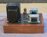
Looking good!
I often look at the bottom side of the Marantz 8 as inspiration for wire routing and layout. They are a work of art.
-

MashBill - Posts: 63
- Joined: Mon Nov 24, 2008 12:43 pm
- Location: Kansas, USA
DK101
![]() by EWBrown » Tue Oct 26, 2010 9:35 am
by EWBrown » Tue Oct 26, 2010 9:35 am
I finally got around to starting the "DK101"" 12B4A SE amp, and decided to see if I could cram it all into and onto a surplus 7.5 X 4.5 X 3 inch cast aluminum Bud box. With a just bit of "creative license", I have made this become a reality
Why have I called it "DK101"
That stands for "Darling Killer" 101. It should have about twice the output power, and approx half of the Darling's 2HD figures.
It uses nearly the same circuitry as the "Darling" 1626 based amp, but with 12B4As instead of 1626s , and a slightly different driver, using a 12AT7WA in place of 12SL7 (or the original 8532s). I had to "shrink" things down in order to get it all to fit in its rather limited space. FWIW, 12DT8 will also work in place of the 12AT7, as it is essentially the same tube, just without the center tapped filament. It is drop-in compatible with this design with 12V filament power.
I had to change from Plan A, using the Hammond 369 EX power trannie, to Plan B, using one of the AnTek 05T200 toriods, in order to get it all to fit neatly.
.
The toriod, THE 22699 CHOKE, and the rest of the PSU components are all mounted in the bottom, and on the rear of the "tub" part of the box, and the two TF103-48 OPTss and the three tubes (2 X 12B4A, 12AT7WA) on the top cover, as well as the speaker binding posts, input RCAs and volume control. A short six-wire "internal umbilical" cable will joint the two sections. I plan to make the final assembly to "hinge" open from the rear, for easy internal access for tests and measurements, and future mods and repairs.
I have already checked out the PSU and, under resistive test load, it delivers the correct B+, and I connected the two 6.3VAC filament windings in series for 12.6VAC CT, as all the tubes have 12.6V filaments, this makes it just a tad simpler, with one less connection to each tube socket I'll keep it simple, with AC filament voltage, as I've had no problems with making this operation totally hum-free.
I have all the top cover'smajor parts, and tube sockets, and terminal strips mounted (all this done on the first day's work). Next step is to gather up all the small components (Rs and Cs) and wire it all up, point to point style.
I'm expecting about 1.65WPC, and max 2HD around 6% at full power output.
Photos of this (and my two recent 6BM8 / 6F3P builds) coming soon...
/ed B
Why have I called it "DK101"
That stands for "Darling Killer" 101. It should have about twice the output power, and approx half of the Darling's 2HD figures.
It uses nearly the same circuitry as the "Darling" 1626 based amp, but with 12B4As instead of 1626s , and a slightly different driver, using a 12AT7WA in place of 12SL7 (or the original 8532s). I had to "shrink" things down in order to get it all to fit in its rather limited space. FWIW, 12DT8 will also work in place of the 12AT7, as it is essentially the same tube, just without the center tapped filament. It is drop-in compatible with this design with 12V filament power.
I had to change from Plan A, using the Hammond 369 EX power trannie, to Plan B, using one of the AnTek 05T200 toriods, in order to get it all to fit neatly.
.
The toriod, THE 22699 CHOKE, and the rest of the PSU components are all mounted in the bottom, and on the rear of the "tub" part of the box, and the two TF103-48 OPTss and the three tubes (2 X 12B4A, 12AT7WA) on the top cover, as well as the speaker binding posts, input RCAs and volume control. A short six-wire "internal umbilical" cable will joint the two sections. I plan to make the final assembly to "hinge" open from the rear, for easy internal access for tests and measurements, and future mods and repairs.
I have already checked out the PSU and, under resistive test load, it delivers the correct B+, and I connected the two 6.3VAC filament windings in series for 12.6VAC CT, as all the tubes have 12.6V filaments, this makes it just a tad simpler, with one less connection to each tube socket
I'll keep it simple, with AC filament voltage, as I've had no problems with making this operation totally hum-free.
I have all the top cover'smajor parts, and tube sockets, and terminal strips mounted (all this done on the first day's work). Next step is to gather up all the small components (Rs and Cs) and wire it all up, point to point style.
I'm expecting about 1.65WPC, and max 2HD around 6% at full power output.
Photos of this (and my two recent 6BM8 / 6F3P builds) coming soon...
/ed B
Last edited by EWBrown on Mon May 16, 2011 3:19 pm, edited 1 time in total.
Real Radios Glow in the Dark
-
EWBrown - Insulator & Iron Magnate
- Posts: 6389
- Joined: Wed Mar 19, 2003 6:03 am
- Location: Now located in Clay County, NC !
![]() by Ty_Bower » Fri Nov 12, 2010 2:31 pm
by Ty_Bower » Fri Nov 12, 2010 2:31 pm
Ty_Bower wrote:...this schematic.

I've got a big sack full of Radio Shack 1/2 watt CF resistors I'd like to try to use up. Is there any reason I couldn't use them for most of this circuit? The cathode resistor R8 needs to be at least 2 or 3 watt rated, and in the power supply R12 (if used) should probably be 2 watts as well. Ed said he used a 1 watt part for R13, but I can't see how that is really necessary. There should be less than 2 mA going through there, which is only 0.08 watt.
EWBrown wrote:Photos of this (and my two recent 6BM8 / 6F3P builds) coming soon...
I shiver with antici...pation.
Last edited by Ty_Bower on Fri Nov 12, 2010 2:41 pm, edited 1 time in total.
"It's a different experience; the noise occlusion, crisp, clear sound, and defined powerful bass. Strong bass does not corrupt the higher frequencies, giving a very different overall feel of the sound, one that is, in my opinion, quite unique."
-
Ty_Bower - KT88
- Posts: 1494
- Joined: Wed Mar 21, 2007 2:50 pm
- Location: Newark, DE
![]() by EWBrown » Fri Nov 12, 2010 2:38 pm
by EWBrown » Fri Nov 12, 2010 2:38 pm
Nothing wrong with using paralleled or series'ed resistors where needed, I've done it more than once. I just use what I have in the junque boxes
/ed B
/ed B
Real Radios Glow in the Dark
-
EWBrown - Insulator & Iron Magnate
- Posts: 6389
- Joined: Wed Mar 19, 2003 6:03 am
- Location: Now located in Clay County, NC !
![]() by azazello » Sun Nov 14, 2010 1:38 pm
by azazello » Sun Nov 14, 2010 1:38 pm
My DIY in Chicago SE 6V6GT Silvania $ 12AT7 Silvania & OTs Hammond 125CSE & PT Hammond 369AX & Chocke Hammond 154M & chasse Hammond 1444
I built for my son:
http://picasaweb.google.com/azazello52/ ... 2692374338
http://picasaweb.google.com/azazello52/ ... 4232646610
Tested with test CD.... We heard 40-18000 khz, sorry we have not some special test stuff. OT tranies are very, veri good....
I built for my son:
http://picasaweb.google.com/azazello52/ ... 2692374338
http://picasaweb.google.com/azazello52/ ... 4232646610
Tested with test CD.... We heard 40-18000 khz, sorry we have not some special test stuff. OT tranies are very, veri good....
-

azazello - KT88
- Posts: 285
- Joined: Tue Nov 10, 2009 8:24 am
- Location: Bulgaria - EU
Two more small amps
![]() by EWBrown » Fri Nov 19, 2010 7:20 pm
by EWBrown » Fri Nov 19, 2010 7:20 pm
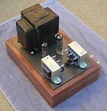
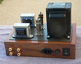
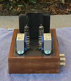
Two more small amps, that I completed last month.
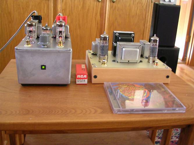
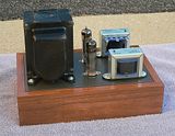
On the left is a 12B4A / 12DT8 SET, the "Darling Killer" built on and into a 4.5X7X3 inch cast aluminum Bud Box. The power supply (using an Antek 05T200) is built into the "tub", along with the electrolytic caps, choke and power switch and fuse, and the little green LED on the front. The amplifier circuit is all on the lid, and is connected to the PSU with a six wire "umbilical" This was designed and built so that I could try other amplifier designs on the existing PSU, with a minimum of wasted efforts. OPTs are the Triode TF103-48s, 5K to 8 ohms. Good for about 1.6WPC and sounds quite nice.
The circuit design is essentially identical to the "Darling" except for the tubes used.
To the right, is my compact 6Ф3П / ECL82 (Russian 6BM8) SEP/UL. It measures about 6.5 X 5.5 inches and the wooden frame is 1.5 inches high. This also uses the Triode TF103-48-UL OPTs, The circuit is that which I described in earlier postings, with two NFB paths, the usual "global" NFB from the OPT secondary to the VA cathode, and an additional plate feedback path by means of a 1 Megohm resistor connected betwen the triode and pentode plates. This addition made a dramatic difference in the sound quality, from very good to "unbelieveably excellent" for such a simple design. It is good for about 2WPC, and I did not have any room inside fir a volume control. Compare the size of the tube box and CD to the two amps. The circuit schematic for the 6F3P amp is about 2 or 3 postings above this one.
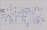
This "thumb" doesn't link, just use the one 3 postings higher up the page.
Both amps' PSUs have the Fender 22699 choke (4H, 90 mA, 105 ohms DCR) and the 6F3P Power trannie is the diminutive 269EX (190-0-190 VAC @ 65 mA and 6.3VAC @ 2.5A) much smaller than those "ten pounder" 7019s from E-bay
Both amps have absolutely no hum or background noise, "is this thing really turned on" quiet
I'll add some "guts shots" later on., as well as some of the larger, more powerful (5WPC) 6Ф3П / ECL82SE-UL design.
/ed B in NC
On the left is a 12B4A / 12DT8 SET, the "Darling Killer" built on and into a 4.5X7X3 inch cast aluminum Bud Box. The power supply (using an Antek 05T200) is built into the "tub", along with the electrolytic caps, choke and power switch and fuse, and the little green LED on the front. The amplifier circuit is all on the lid, and is connected to the PSU with a six wire "umbilical" This was designed and built so that I could try other amplifier designs on the existing PSU, with a minimum of wasted efforts. OPTs are the Triode TF103-48s, 5K to 8 ohms. Good for about 1.6WPC and sounds quite nice.
The circuit design is essentially identical to the "Darling" except for the tubes used.
To the right, is my compact 6Ф3П / ECL82 (Russian 6BM8) SEP/UL. It measures about 6.5 X 5.5 inches and the wooden frame is 1.5 inches high. This also uses the Triode TF103-48-UL OPTs, The circuit is that which I described in earlier postings, with two NFB paths, the usual "global" NFB from the OPT secondary to the VA cathode, and an additional plate feedback path by means of a 1 Megohm resistor connected betwen the triode and pentode plates. This addition made a dramatic difference in the sound quality, from very good to "unbelieveably excellent" for such a simple design. It is good for about 2WPC, and I did not have any room inside fir a volume control. Compare the size of the tube box and CD to the two amps. The circuit schematic for the 6F3P amp is about 2 or 3 postings above this one.
This "thumb" doesn't link, just use the one 3 postings higher up the page.
Both amps' PSUs have the Fender 22699 choke (4H, 90 mA, 105 ohms DCR) and the 6F3P Power trannie is the diminutive 269EX (190-0-190 VAC @ 65 mA and 6.3VAC @ 2.5A) much smaller than those "ten pounder" 7019s from E-bay
Both amps have absolutely no hum or background noise, "is this thing really turned on" quiet
I'll add some "guts shots" later on., as well as some of the larger, more powerful (5WPC) 6Ф3П / ECL82SE-UL design.
/ed B in NC
Last edited by EWBrown on Thu Feb 23, 2017 5:20 pm, edited 5 times in total.
Real Radios Glow in the Dark
-
EWBrown - Insulator & Iron Magnate
- Posts: 6389
- Joined: Wed Mar 19, 2003 6:03 am
- Location: Now located in Clay County, NC !
Who is online
Users browsing this forum: No registered users and 61 guests