12B4As with a 5K OPT work best with a B+ between 240 and 250VDC, and plate current around 25-27 mA, cathode resistor of 1K, 5W, suitably bypassed IIRC, 242-245 VDC is the "sweet spot", power output around 1.5W maximum. The 1626 is good for about half that power level, with identical circuitry. I suppose that one could parallel connect an octal and a 9 pin tube socket in order to make the SE amp "convertible" to either tube. I wouldn't bother with any "fancy" multipole switching schemes, here...
With higher Z OPTs (22-24K), the 12B4As are happier with B+ around 300-325V and plate current around 17-18 mA, and a cathode resistor of 2.2 to 2.4K, 5W, also suitably bypassed This gives a "sweeter" sound quality , but at the expense of lower power output, around 900 mW max. The driver also has to have about 4dB more voltage gain than with the first setup.
6S4As aren't trully "happy" with less than 11K OPT, and the 22-24K is a real sweet performer. B+ of 325V, plate current 22-25 mA, rK = 390 - 430 ohms, 2W They also work very nicely in PSE or PPP aplications, all well-covered elsewhere on this forum, a couple years ago.
The Russian 6C19s have some interesting possibilities, but they require a much higher negative grid to cathode bias voltage, around 80-100VDC, and the driver has to develop a healthy "swing" to properly drive them. I've only worked these out on paper, so far, so I can't rate them as good or poor, yet.
/ed B
My low watts projects
![]() by azazello » Sun Sep 19, 2010 3:32 pm
by azazello » Sun Sep 19, 2010 3:32 pm
One of my 2010 y-s projects....SE 6S4S
http://picasaweb.google.bg/azazello52/A ... 6716888210
http://picasaweb.google.bg/azazello52/A ... 6716888210
-

azazello - KT88
- Posts: 285
- Joined: Tue Nov 10, 2009 8:24 am
- Location: Bulgaria - EU
![]() by azazello » Fri Sep 24, 2010 7:00 am
by azazello » Fri Sep 24, 2010 7:00 am
I counted output trany with alpha 10!!! I loosed little bit output power, but
bass now is killer and very strong....more than bass 6S33S! I used iron
Ш 0,2 mm from brand Pacific Transformer. Ra is 8 kohm /Ri is 800 ohms/.
Coils 1-2-1.
bass now is killer and very strong....more than bass 6S33S! I used iron
Ш 0,2 mm from brand Pacific Transformer. Ra is 8 kohm /Ri is 800 ohms/.
Coils 1-2-1.
-
azazello - KT88
- Posts: 285
- Joined: Tue Nov 10, 2009 8:24 am
- Location: Bulgaria - EU
![]() by EWBrown » Wed Sep 29, 2010 4:59 pm
by EWBrown » Wed Sep 29, 2010 4:59 pm
Those vintage twin-plate 6S4S / 6C4C are very nice sounding, I also have a collection of these, also with the Svetlana "winged C" marking.
These are the Russian version of the USA made 6B4G. The newer 6S4S / 6C4C are the single plate version and have a somewhat higher plate dissipation (around 20 W) , as does the Sovtek single plate 2A3 / 2C4C.
The latest completed project is a small 6BM8 (actually vintage Russian Winged C Svetlana 6F3P) SEP.
These also have the QA "Diamond" and teh letters OTK, which is the initials for Oтдел Техническово Контроля, or "technical control bureau". Pronounced something akin to "Otdyel Kontrolya Technitcheskovo"
Pretty much the standard posted circuitry, but I set it up for UL operation with Triode TF1-103-48-UL opts. I also took an idea from the RH-84 design and added "plate feedback" from the power pentode plate (pin 6) to pin 9 of the VA triode. This REALLY made a huge difference, from an "OK" sounding amp, to an amazingly good sounding one, considering the simplicity of the circuitry and inexpensive parts. It also has the "global
NFB from OPT to VA cathode, but that didn't have much of an effect, and nearly nothing, as compared to the added 1 meg PFB resistor.
I used a cast-off 6.5 X 7.5 inch aluminum plate for the chassis, and made a simple wooden base with some 1.5X 0.75 "fancy" trim wood. Wan't enough room for a volume control, but that's not a major problem for my setup.. The power trannie is Hammond 269EX, and I used the 4H, 90 mA Triode Electronics 22699 choke, which is about the size of an enclosed C354 choke. It's like trying to put ten pounds of ( bovine fertilizer) in a five pound bag.
This was just a "hack" and I really wasn't expecting much, but I was pleasantly surprised

Photos to be posted soon....
/ed B
These are the Russian version of the USA made 6B4G. The newer 6S4S / 6C4C are the single plate version and have a somewhat higher plate dissipation (around 20 W) , as does the Sovtek single plate 2A3 / 2C4C.
The latest completed project is a small 6BM8 (actually vintage Russian Winged C Svetlana 6F3P) SEP.
These also have the QA "Diamond" and teh letters OTK, which is the initials for Oтдел Техническово Контроля, or "technical control bureau". Pronounced something akin to "Otdyel Kontrolya Technitcheskovo"
Pretty much the standard posted circuitry, but I set it up for UL operation with Triode TF1-103-48-UL opts. I also took an idea from the RH-84 design and added "plate feedback" from the power pentode plate (pin 6) to pin 9 of the VA triode. This REALLY made a huge difference, from an "OK" sounding amp, to an amazingly good sounding one, considering the simplicity of the circuitry and inexpensive parts. It also has the "global
NFB from OPT to VA cathode, but that didn't have much of an effect, and nearly nothing, as compared to the added 1 meg PFB resistor.
I used a cast-off 6.5 X 7.5 inch aluminum plate for the chassis, and made a simple wooden base with some 1.5X 0.75 "fancy" trim wood. Wan't enough room for a volume control, but that's not a major problem for my setup.. The power trannie is Hammond 269EX, and I used the 4H, 90 mA Triode Electronics 22699 choke, which is about the size of an enclosed C354 choke. It's like trying to put ten pounds of ( bovine fertilizer) in a five pound bag.
This was just a "hack" and I really wasn't expecting much, but I was pleasantly surprised
Photos to be posted soon....
/ed B
Last edited by EWBrown on Sat Oct 16, 2010 8:10 pm, edited 6 times in total.
Real Radios Glow in the Dark
-

EWBrown - Insulator & Iron Magnate
- Posts: 6389
- Joined: Wed Mar 19, 2003 6:03 am
- Location: Now located in Clay County, NC !
![]() by Ty_Bower » Wed Sep 29, 2010 5:47 pm
by Ty_Bower » Wed Sep 29, 2010 5:47 pm
EWBrown wrote:The latest completed project is a small 6BM8...
Photos to be posted soon.
I'm keenly interested. Please do include a schematic, if you have one.
"It's a different experience; the noise occlusion, crisp, clear sound, and defined powerful bass. Strong bass does not corrupt the higher frequencies, giving a very different overall feel of the sound, one that is, in my opinion, quite unique."
-

Ty_Bower - KT88
- Posts: 1494
- Joined: Wed Mar 21, 2007 2:50 pm
- Location: Newark, DE
![]() by EWBrown » Thu Sep 30, 2010 6:16 pm
by EWBrown » Thu Sep 30, 2010 6:16 pm
My schematic is based on this one, which is fairly typical for this tube:
http://cool386.tripod.com/6bm8/6BM8.html
(I tried linking the image, but it just shows a "Tripod" logo)

I started out with this diagram, and did a lot of pencil "editing", so it is rather a scribbled mess right now... I used two Russian (Svetlana 6Ф3П / ECL82 as I have plenty of these on hand.
The major modification was to connect a 1 megohm resistor between the two plates (pins 6 and 9), which is a 1940's vintage method of introducing NFB. It is also used in the "RH84" EL84 based amps.
I eliminated most everything before the VA tube's grid, and used 100K across the RCA conenctor, and 4.7K grid stopper . The power section, I changed the cathode resistor from 390 ohms to 470 ohms, 2W, in order to keep the plate dissipation at 7 Watts. I left in the original NFB, but it didn't seem to have much effect whether it was in or out of the curciit. The plate feedback has a very noticeable effect, and really improves the sound quality from the original configuration.
For UL, I used a 100 ohm resistor from screen grid to the SG tap on the TF103-48-UL trannie (white lead).
Eliminate the 2.2K SG resistor shown in the schematic, as it is no longer needed.
For the pentode grid resistor, I used 270K instead of 470K, and the interstage coupling cap, 0.1 uF instead of 0.047 uF. I did this to eliminate (or at least reduce) any possible grid emission problems with these high-gm pentodes, as suggested in the original article.
The PSU is simple, Hammond 269 X (190-0-190 @ 65 mA, 6.3VAC @ 2.5A), two UF4007s, into a 100 ohm 5W WW resistor (this resistor can be changed in value, or eliminated as needed) , into a 40 uF / 450V cap, across a Triode 22699 choke (4H, 90 mA, 105 ohms DCR) into a 180 uF frov Cap, which delivers about 231 VDC at 72 mA current consumption. The trannie is nominally rated at 65 mA, but I've gently pushed these several mA beyond that, with no problems. Just don't try to run 4 6BM8s off it, it will most likely blow up into a flaming smoky mess under that kind of abuse
I was pleasantly surprised by the TF103-48-ULs, for such small "smurf-size" OPTs they do a very nice job, and the freq response is better than I expected.
THe next version, I'll try PSE, with two 6Ф3П / ECL82 per channel, maybe SRPP drivers (or VA-CF) in order to use all the triode sections. OPTs can be 2.5 to 3K, and should be good for at least 5 WPC.
/ed B
http://cool386.tripod.com/6bm8/6BM8.html
(I tried linking the image, but it just shows a "Tripod" logo)
I started out with this diagram, and did a lot of pencil "editing", so it is rather a scribbled mess right now...
I used two Russian (Svetlana 6Ф3П / ECL82 as I have plenty of these on hand.The major modification was to connect a 1 megohm resistor between the two plates (pins 6 and 9), which is a 1940's vintage method of introducing NFB. It is also used in the "RH84" EL84 based amps.
I eliminated most everything before the VA tube's grid, and used 100K across the RCA conenctor, and 4.7K grid stopper . The power section, I changed the cathode resistor from 390 ohms to 470 ohms, 2W, in order to keep the plate dissipation at 7 Watts. I left in the original NFB, but it didn't seem to have much effect whether it was in or out of the curciit. The plate feedback has a very noticeable effect, and really improves the sound quality from the original configuration.
For UL, I used a 100 ohm resistor from screen grid to the SG tap on the TF103-48-UL trannie (white lead).
Eliminate the 2.2K SG resistor shown in the schematic, as it is no longer needed.
For the pentode grid resistor, I used 270K instead of 470K, and the interstage coupling cap, 0.1 uF instead of 0.047 uF. I did this to eliminate (or at least reduce) any possible grid emission problems with these high-gm pentodes, as suggested in the original article.
The PSU is simple, Hammond 269 X (190-0-190 @ 65 mA, 6.3VAC @ 2.5A), two UF4007s, into a 100 ohm 5W WW resistor (this resistor can be changed in value, or eliminated as needed) , into a 40 uF / 450V cap, across a Triode 22699 choke (4H, 90 mA, 105 ohms DCR) into a 180 uF frov Cap, which delivers about 231 VDC at 72 mA current consumption. The trannie is nominally rated at 65 mA, but I've gently pushed these several mA beyond that, with no problems. Just don't try to run 4 6BM8s off it, it will most likely blow up into a flaming smoky mess under that kind of abuse
I was pleasantly surprised by the TF103-48-ULs, for such small "smurf-size" OPTs they do a very nice job, and the freq response is better than I expected.
THe next version, I'll try PSE, with two 6Ф3П / ECL82 per channel, maybe SRPP drivers (or VA-CF) in order to use all the triode sections. OPTs can be 2.5 to 3K, and should be good for at least 5 WPC.
/ed B
Last edited by EWBrown on Wed May 08, 2013 7:29 pm, edited 2 times in total.
Real Radios Glow in the Dark
-
EWBrown - Insulator & Iron Magnate
- Posts: 6389
- Joined: Wed Mar 19, 2003 6:03 am
- Location: Now located in Clay County, NC !
![]() by dhuebert » Fri Oct 01, 2010 7:21 am
by dhuebert » Fri Oct 01, 2010 7:21 am
I order you to post a schematic. OOO, order eh? Who does he think he is? Oh, king eh? Very nice.
Don
http://www.youtube.com/watch?v=rAaWvVFERVA
Don
http://www.youtube.com/watch?v=rAaWvVFERVA
-

dhuebert - KT88
- Posts: 820
- Joined: Thu May 01, 2003 9:26 am
- Location: Winnipeg Manitoba Canada
![]() by Ty_Bower » Fri Oct 01, 2010 10:53 am
by Ty_Bower » Fri Oct 01, 2010 10:53 am
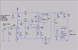
Please, check this schematic Ed. I think this is what you wrote up.
I still want to see photos of your wiring.

I still want to see photos of your wiring.
"It's a different experience; the noise occlusion, crisp, clear sound, and defined powerful bass. Strong bass does not corrupt the higher frequencies, giving a very different overall feel of the sound, one that is, in my opinion, quite unique."
-
Ty_Bower - KT88
- Posts: 1494
- Joined: Wed Mar 21, 2007 2:50 pm
- Location: Newark, DE
![]() by soundbrigade » Fri Oct 01, 2010 10:59 am
by soundbrigade » Fri Oct 01, 2010 10:59 am
I successfully tried this design based on the Super Triode Connection principle:
Magnus
"It is always more difficult to fight against faith than against knowledge."
"It is always more difficult to fight against faith than against knowledge."
-

soundbrigade - KT88
- Posts: 1760
- Joined: Mon Jan 28, 2008 4:57 am
- Location: Little Paris, Sweden
![]() by EWBrown » Sat Oct 02, 2010 10:08 am
by EWBrown » Sat Oct 02, 2010 10:08 am
You have it about 95%. right! I also put in a 20K 1W decoupling resistor between the PA and VA B+, along with the 22 uF/450V cap (see next). If you want possibly more channel separation, use a 39K resistor and a 10-16 uF / 350V (or greater) cap for each channel.
I feed both VAs off the 20K resistor and the 22 uf Cap. This resistor is probably not absolutely necessary, but I like to follow the "old school" line of design thought, and just put it in. With both VA stages, the current consumption is about 1.2 mA, and the voltage drop about 24 VDC.
Each PA stage draws about 35-36 mA, so the total B+ (231 VDC) current consumption is 71-73 mA, which is 6 to 8 mA above the HV winding's published max ratings, but then I am also drawing about an amp less than the filament winding's max rating, so I figure that the load on the primary still stays well within the ratings. The 269EX trannie gets warm after a few hours' operation, but not overly hot to the touch - a PA774 in an ST35 gets significantly hotter.
I used 4.7K instead of 47K for the pentode grid stopper R7. I also used some different component values for C1 (22 uF / 450V), C2 (47 uF / 10V) C4 (330 uF / 50V MUSE Cap), just because these were what I had on hand. None of these actual values changes (except possibly R7) will have any noticeable effect on the amp's overall operation.
The real "secret" to the improved sound quality is the plate-to-plate NFB effected by adding the 1 Meg resistor R10. the other NFB loop has little or no effect, and could be left out, just eliminate the 150 ohm resistor, and the 4.7K & .001 uF NFB path. I just left it in, because trying to remove it would be very difficult due to the very close spacing and compact structure.
I measured the TF103's primary inductance last year, and I found them to be very close to 10H, from P to B (red to blue) leads. That inductance value definitely helps the LF response. For such puny sized OPTs they sould pretty darn good I'm sure that full sized Edcors would be a major inprovement, as would any "fancy" OPTs.
In place of the 100K input resistor, a 100K stereo pot can be used, if desired. I just left out the VC because I didn't have enough room under the chassis plate (the wood frame consumes about 3/4 inch from each side, so that left me with approximately 6X5 inch under the chassis plate.
For the next version, I plan to go with PSE, and maybe use some 3K OPTs that I have, these have no UL taps, so I'll be limited to either triode or pentode modes with these. Or I'll order some iron from Edcor and wait until hell freezes over, errrrr, for the 8 weeks for them to be delivered...
I won't bother with any more PP 6BM8 designs, as I've already built up a couple of the K502 11BM8 / 16A8 designs, and I've done all the reasonable mods to get them sounding better. IMHO, the SE sounds nicer than the PP does, though at lower power levels.
Here are the actual voltage measurements (rounded off) from my amp:
B+ = 231 VDC
6BM8:
pin 8: 1.42 VDC
pin 9: 102 VDC
pin 2 16.8 VDC
pin 6: 219 VDC
pin 7: 227 VDC
Pins 1 & 3: 0.0 VDC
Pins 4 & 5: 6.5VAC, 3.25VAC each to ground
PSU:
UF4007 cathodes: 247VDC
100 OHM WW: about 8VDC drop
+ of 40 uF cap: 239 VDC
choke: about 8VDC drop
+ of 180 uF cap: 231 VDC (B+)
filament: 6.5 VAC
/ed B
I feed both VAs off the 20K resistor and the 22 uf Cap. This resistor is probably not absolutely necessary, but I like to follow the "old school" line of design thought, and just put it in. With both VA stages, the current consumption is about 1.2 mA, and the voltage drop about 24 VDC.
Each PA stage draws about 35-36 mA, so the total B+ (231 VDC) current consumption is 71-73 mA, which is 6 to 8 mA above the HV winding's published max ratings, but then I am also drawing about an amp less than the filament winding's max rating, so I figure that the load on the primary still stays well within the ratings. The 269EX trannie gets warm after a few hours' operation, but not overly hot to the touch - a PA774 in an ST35 gets significantly hotter.
I used 4.7K instead of 47K for the pentode grid stopper R7. I also used some different component values for C1 (22 uF / 450V), C2 (47 uF / 10V) C4 (330 uF / 50V MUSE Cap), just because these were what I had on hand. None of these actual values changes (except possibly R7) will have any noticeable effect on the amp's overall operation.
The real "secret" to the improved sound quality is the plate-to-plate NFB effected by adding the 1 Meg resistor R10. the other NFB loop has little or no effect, and could be left out, just eliminate the 150 ohm resistor, and the 4.7K & .001 uF NFB path. I just left it in, because trying to remove it would be very difficult due to the very close spacing and compact structure.
I measured the TF103's primary inductance last year, and I found them to be very close to 10H, from P to B (red to blue) leads. That inductance value definitely helps the LF response. For such puny sized OPTs they sould pretty darn good
I'm sure that full sized Edcors would be a major inprovement, as would any "fancy" OPTs.In place of the 100K input resistor, a 100K stereo pot can be used, if desired. I just left out the VC because I didn't have enough room under the chassis plate (the wood frame consumes about 3/4 inch from each side, so that left me with approximately 6X5 inch under the chassis plate.
For the next version, I plan to go with PSE, and maybe use some 3K OPTs that I have, these have no UL taps, so I'll be limited to either triode or pentode modes with these. Or I'll order some iron from Edcor and wait until hell freezes over, errrrr, for the 8 weeks for them to be delivered...
I won't bother with any more PP 6BM8 designs, as I've already built up a couple of the K502 11BM8 / 16A8 designs, and I've done all the reasonable mods to get them sounding better. IMHO, the SE sounds nicer than the PP does, though at lower power levels.
Here are the actual voltage measurements (rounded off) from my amp:
B+ = 231 VDC
6BM8:
pin 8: 1.42 VDC
pin 9: 102 VDC
pin 2 16.8 VDC
pin 6: 219 VDC
pin 7: 227 VDC
Pins 1 & 3: 0.0 VDC
Pins 4 & 5: 6.5VAC, 3.25VAC each to ground
PSU:
UF4007 cathodes: 247VDC
100 OHM WW: about 8VDC drop
+ of 40 uF cap: 239 VDC
choke: about 8VDC drop
+ of 180 uF cap: 231 VDC (B+)
filament: 6.5 VAC
/ed B
Last edited by EWBrown on Wed Jun 04, 2014 7:04 pm, edited 2 times in total.
Real Radios Glow in the Dark
-
EWBrown - Insulator & Iron Magnate
- Posts: 6389
- Joined: Wed Mar 19, 2003 6:03 am
- Location: Now located in Clay County, NC !
![]() by Ty_Bower » Sat Oct 02, 2010 3:04 pm
by Ty_Bower » Sat Oct 02, 2010 3:04 pm
EWBrown wrote:You have it about 95%. right!
The schematic has been updated.
I didn't change the inductance of the output transformer because it's a pain for me to figure out the screen tap. For what you get out of the model, I don't think it's that critical anyway.
Any photos of the wiring?
"It's a different experience; the noise occlusion, crisp, clear sound, and defined powerful bass. Strong bass does not corrupt the higher frequencies, giving a very different overall feel of the sound, one that is, in my opinion, quite unique."
-
Ty_Bower - KT88
- Posts: 1494
- Joined: Wed Mar 21, 2007 2:50 pm
- Location: Newark, DE
![]() by EWBrown » Sat Oct 02, 2010 7:46 pm
by EWBrown » Sat Oct 02, 2010 7:46 pm
I haven't yet photographed it, and the under-chassis wiring is a bit stacked and crowded, and some of the smaller parts aren't readily visible. I'll get it done in the next couple days. There are a couple of minor physical layout blunders, but they don't really show up all that much, except perhaps to the trruly critical observer
The new schematic looks 100% good!
I forgot to mention, I put in a 330K, 1W bleeder resistor across the 180 uF cap, but that won't affect the operation, it's just a safety feature, which I use in ALL of my tube amp designs. It will add another 700 microamps to the current loading
This whole thing originally was intended to be a 12B4A & 12AX7 design, but it didn't take too long for me to determine that three (or four) tubes and all the support components weren't going to fit onto the limited space too well, so I dug up the 6F3Ps, just to be sure that I still had them (got 'em on e-prey about 5 years ago from Gintaras).
I laid out the PSU and the two OPTs, first, and then determined the remaining usable chassis plate space, which was a tad tight, even for 6BM8s. No, it would never be a true contender in the "tiny amp" design contest...
I probably can still do the 12B4A design, with a bit of tighter spacing, that will be a future project, I have several of these oddball aluminum plates, which were originally internal top shield plates from a "work" project that never got off the ground. Better than just seeing them go "clang" into the dumpster... Waste not, want not
/ed B
Real Radios Glow in the Dark
-
EWBrown - Insulator & Iron Magnate
- Posts: 6389
- Joined: Wed Mar 19, 2003 6:03 am
- Location: Now located in Clay County, NC !
![]() by katabatic » Sun Oct 03, 2010 11:49 am
by katabatic » Sun Oct 03, 2010 11:49 am
EWBrown wrote:I've had excellent results in the 1 watt or less class using 12B4As and 6S4As (not to be confused with Russian 6C4C / 6S4S triodes) as well as 6BL7s SET amps, these are good with both triodes connected in parallel.
For 12B4As, just copy the basic "Darling" SET circuit, but use 12B4As in place of the 1626s.
/ed B in NC
OK, I admit to not being terribly bright or skilled at this stuff so far (on the other hand, I haven't electrocuted myself either...yet). So if I wanted to try 12B4A's and a 12AX7 in the Darling circuit shown on Tom McNally's site, is it a straight substitution (with the appropriate pin connections), where I just leave pin 3 on the 12 B4A's and pin 9 on the 12 AX7 unconnected (the heater center-tap pins)? That would get 12.6 volts to the heater, right? (The GE data sheet for the 12AX7 says "A center-tapped heater permits operation of the tube from either a 6.3 or a 12.6 heater supply.") So I'm a bit confused.
Anything else I should be aware of? Thanks.
George
-
katabatic - Posts: 48
- Joined: Mon Mar 29, 2010 6:52 pm
- Location: Oak Hill, Virginia
Who is online
Users browsing this forum: No registered users and 35 guests