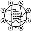
I'm trying to design an input/splitter frontend for a 6F6 amplifier. I'm looking to use a 6EM7 tube per channel.
Here's what I've got so far. I'm biasing the high-gain section (using TubeCAD's 12AT7 numbers) at 1.2V on the cathode (787 Rk, 1.5mA Ia) , with a 49K plate resistor and B+ of 180V. I have 106V on the plate. Now, how the heck to I bias the bigger section? I've got the plate curves in front of me but I don't understand how to find a reasonable bias point while still keeping Ra and Rk exactly the same... Am I missing something incredibly simple here?
P.S. the maximum B+ I have to work with is 300V or so. I'm using an original PA774 going mostly choke input to a 193J (10H 200mA). I'm tuning it to put out 300V, as opposed to 400V or more, so I can expect a bit more than 180mA from it, right? Each 6F6 is at 40mA, so I have at least 20mA for both channels' frontends, quite possibly more..
Thanks for the help!
Direct-Coupled Question
4 posts
• Page 1 of 1
Sorenj07,
Just about every amp design works best when designing from output back toward input.
I take it you want to run the higher power triode as a split load (concertina) phase inverter.
Start with the expected rail voltage.
You want equal voltages across the anode and cathode resistors AND across the triode itself (Rule of thumb).
So B+ of 180 => Va = 120V, Vk = 60V
Work out Ra and Rk from the current you want to use.
That Vk defines what you need on the grid, if for example that current and that Vak requires -3V from grid to cathode then the grid will want to sit at 60-3=57 volts.
NOW go back to the front end and try to achieve +57 anode voltage.
It is unforunate that the 6EM7 is not really that suitable for what you are trying to do with it. Not at +180V rail anyway. 180 is too low for concertina splitters (generally).
So turn the envelope over and start scribbling Plan B on the clean side. From the above you can see we come unstuck because B+ was too low. Concertina Splitters really need some rail volts to work with. Start with B+ >= 300V and repeat.
If you have Morgan Jones "Valve Amplifiers" handy look at his design notes for the "Bevois Valley" Amp. He used ECC88 with a B+ of 285V and managed to manipulate the currents in the two triode sections to be the same (less demands on the power supply as net AC current draw is 0).
If using something like a 12AT7 then a higher rail works better - say 360V which you could get by using a voltage doubler in lieu of whatever you had planned.
A heap of triode pentode tubes are also often used such as the 6AN8, 6U8 etc with the pentode section triode strapped as the 1st amp and the triode section as the concertina splitter - lots of old amps like the Dynaco ST70 and some Ampeg Guitar Amps used this arrangement.
Cheers,
Ian
- Gingertube
- Posts: 245
- Joined: Thu Oct 05, 2006 10:27 pm
- Location: Adelaide, South Oz
Thanks for the info! It was just an idea I had. I'm also considering a standard 6SL7 fed with a high negative voltage source through a tail. Won't be able to drive the amp as far into positive grid territory though. Maybe some interstage transformers are in order?
-

sorenj07 - KT88
- Posts: 925
- Joined: Tue May 02, 2006 2:39 pm
- Location: Berlin
4 posts
• Page 1 of 1
Who is online
Users browsing this forum: No registered users and 56 guests
