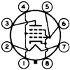
According to Bottlehead & co, the CCS can offer more gain with a given tube, as it acts almost as an "infinite" plate resistance, but at the same time, it sets the tube's operating plate current, as would a normal value plate resistor. The BH typpical driver for a 2A3 or 300B is one 12AT7 / ECC81 section, set around 3.5 mA with a CCS in the plate circuit. The other triode section is unused in some cases, or employed in a shunt regulator, in others.
Some folks like the CCS sound, and some just plain don't... I've used it (in a few Bottlehead amp kit builds) and liked the results, but as with anything, it does increase the circuitry's complexity and can decrease its reliability.
Some say that if one surrounds a tube with transistors, then one ends up with a "transistor sound" Yellow_Light_Colorz_PDT_02
The one case where a CCS reaally "shines" is when it acting as the "tail" resistor in a Tong Tail Phase Splitter. This can set the current and not require the high negative voltage ssupply for the normally high-value "tail" resistor.
Another "Trick" is to use an LED as a cathode resistor, there is some discussion of this in the G*S*G topic. Generally a red LED is used, and the tube's cathode voltage has to be around 1.6 to 1.8VDC above ground (zero volts) . LEDs have a fairly low effective resistance, and do not need capacitor bypassing.
HTH
/ed B in NH (still waking up on this rainy cold first day of "spring"...
Single-Ended 6S19P (Again..)
19 posts
• Page 2 of 2 • 1, 2
THe 12AT7 SRPP should do the trick, nice and easy... To get the 300V to both power and VA stages, the easy way is to split right at the cathode(s) of the rectifier and the first "bulk" cap, a higher current choke to feed the 6S1Ps, and a lower current choke to feed the 12AT7s. It's a bit bit unconventional. just think of as a split CLCLC approach. that way, you don't have to drop the 6S19P's B+ an additional 20-50VDC, in order to decouple the 12AT7's B+ voltage.
The first "C" right off the rectifier should be a pretty hefty device, more capacitance, less sag, etc... It's performing "double duty" in a sense...
Two of the 12AT7 SRPPs should draw no more tha 5 mA, so one of the low current, higher inductance Hammond (or similar) chokes should do the trick.
/ed B in NH
Real Radios Glow in the Dark
-

EWBrown - Insulator & Iron Magnate
- Posts: 6389
- Joined: Wed Mar 19, 2003 6:03 am
- Location: Now located in Clay County, NC !
Yeah, that sounds like it should work. A low-DCR (3H 86R) choke after the 300V supply basically leaves it right at 300V into 4mA (two 12AT7 SRPP's) so I'll probably go with that. The first choke after the voltage doubler will probably be a 193H (5H 200mA), and there's going to be another LC (1.5H 56R) before the B+ supply anyway, so ripple should be reasonably attenuated. Of course this is still all in the air as all I have is the actual isolation transformer at the moment...
-

sorenj07 - KT88
- Posts: 925
- Joined: Tue May 02, 2006 2:39 pm
- Location: Berlin
19 posts
• Page 2 of 2 • 1, 2
Who is online
Users browsing this forum: No registered users and 56 guests
