The Lucky Thirteen: Parallel Feed 13EM7s Spud Amp

the thermionic watercooler

Postby Geek » Fri Jun 19, 2009 11:22 pm

MashBill wrote:Please tell us more about that attenuator....


Ed got bored? (lol)

Looks gorgeous Ed! [:)

Cheers!
-= Gregg =-
Fine wine comes in glass bottles, not plastic sacks. Therefore the finer electrons are also found in glass bottles.
User avatar
Geek
KT88
 
Posts: 3585
Joined: Sun Oct 21, 2007 3:01 am
Location: Chilliwack, British Columbia

Postby SDS-PAGE » Mon Jun 22, 2009 11:53 am

That's cool. I love to see those hardwired amps anytime over amps with PCBs. Nice job! Min
User avatar
SDS-PAGE
KT88
 
Posts: 865
Joined: Thu Feb 22, 2007 4:41 pm
Location: Brandon, SD

Postby EWBrown » Mon Jun 29, 2009 10:06 am

The step attenuator was from Hong Kong (probably built in China) from an E-bay vendor, purchased about 3 years ago.

At the (approx $50) price, I could not have purchased just the switch and resistors, from Mouser or other US vendors. I couldn't have done such a nice job, without landing myself in the local booby hatch (lol) =:o :P in the process.

The resistors are all 1% Dale / Vishay units, and the hand soldering and assembly is absolutely meticulous. The same thing made in USA would probably cost over $200.

These come in the "radial" format, as installed in this amp, and an "axial" format which has a smaller diameter, but a longer overall length. The radial format was best for this build, and is too large to front mount on a 2 inch deep chassis.

There are always several Asian e-bay sellers offering these step attenuators (one calls them "steeped" attenuators).

/ed B
Real Radios Glow in the Dark
User avatar
EWBrown
Insulator & Iron Magnate
 
Posts: 6389
Joined: Wed Mar 19, 2003 6:03 am
Location: Now located in Clay County, NC !

Its little brother

Postby EWBrown » Wed Jun 02, 2010 6:36 pm

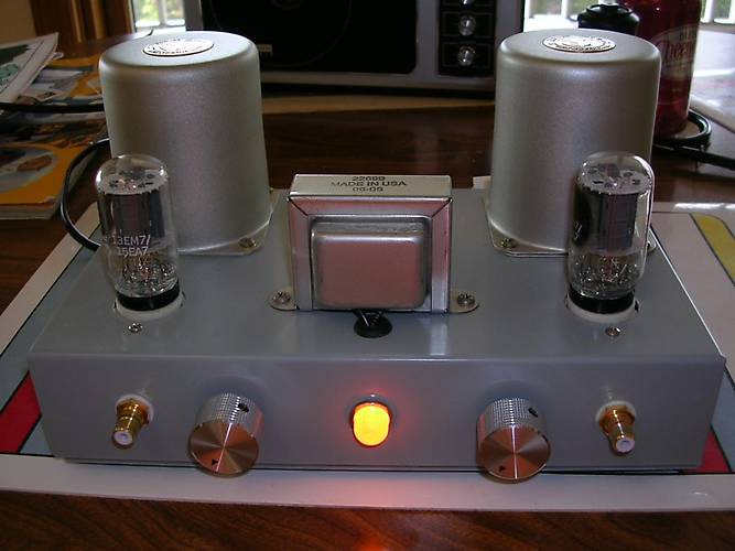
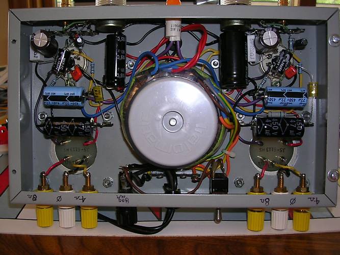
I did previously mention a series-feed, smaller version of the Lucky thirteen, I finally remembered to post its photos...

Image

Top / Frontal view:

Image

Under the chassis "guts shot" :

Image

I simplified the "floating filaments capacitor grounding scheme, and it is still ultra-quiet.

The pilot light is a 28V incandescent unit which I picked out of a box of engineering samples which was labelled "Bright Ideas".

Stay tuned for Version Three...

Update, 1-Dec-2010: After many hours' operatinng this particular amp, it is rapidly becoming one of my favorites. The 5K James OPTs really play very nicely with the 13EM7s in this design, and the sound is far better than I originally expected or hoped that it would be.

For curiosity, I did try the 3.5K primary tap, but the sound was gritty and kinda nasty, though it was definitely louder, and that combination of 3.5K OPT might make for a nice "spud" small guitar amp, in which excessive amounts of THD isn't considered as being a bad thing.

/ed B
Last edited by EWBrown on Mon Feb 14, 2011 7:40 pm, edited 2 times in total.
Real Radios Glow in the Dark
User avatar
EWBrown
Insulator & Iron Magnate
 
Posts: 6389
Joined: Wed Mar 19, 2003 6:03 am
Location: Now located in Clay County, NC !

AnTek 05T200 and load test results

Postby EWBrown » Mon Aug 02, 2010 5:08 pm

There is now a possibly good alternative low-cost toroidal power transformer for this design, from An-Tek.. It is the 50VA rated 05T200, which has two 115V primaries, one HV secondary with 200VAC (and tapped at 180VAC) @ 150 mA, and two 6.3V, @ 2A filament windings.

Image

The filament windings could be connected in series for using 13EM7s, or used for feeding the two separate 6EM7 filaments. THis trannie also has sufficient VA capability to power up a stereo PP 6EM7 or 13EM7 amp.

The 05T200 costs $25, plus $5 shipping, and these have appeared on johnango's e-bay listings, though not yet on teh AnTEk product listings..

Dimensions are 3.7 inches diameter X 1.6 inches height, so it can be mounted under a standard 2 inch deep chassis.

Update 6-Aug-2010:

I received two of these trannies today, and since the 6.3VAC windings are teh outermost windings, it was easy to count the turns, and both have 47 turns, for 6.3V which works out to 7 1/2 turns per volt. Since, with a toroid, there is no such thing as a "half turn, let's just call it 15 turns for 2VAC. Should be pretty easy to add an extra winding, if needed.

I think that the next incarnation of "Lucky thirteen" wmay use 6FD7s, as these trannies may be a good PSU match, and I have about a dozen 6FD7s looking for "gainful" employment. I suppose that to stick with the theme, 13FD7s could be used... I've already worked up circuits for "spud" SET and for SRPP, PSET using 2 tubes per channel. A few simple changes, and this could also be PP.

Update 7-Aug-2010:

I performed some operational tests using the 200VAC output on these transformers, using a FWB rectifier and 140 uF (40 uF and 100 uF cap in parallel, I've used this same setup for testing other trannies).

It does fall somewhat short of producing the optimum B+ voltage ( approx 270-280 VDC) for the 6EM7 / 13EM7 /6 6FD7 spud amps, by about 24VDC, under a 74 mA DC test load. But, a few resistor and OPT primary impedance adjustments should make up for this.

I loaded the DC voltage, progressively with 10K, 10W WW resistors, adding one at a time in parallel, and with 1.2 amp filament loads (6AV5GAs) on each of the two 6.3VAC filament windings, and then recorded the following results:

No load: 280VDC @ 0 mA (200VAC secondary)

10K load: 263VDC @ 26.3 mA

5K load: 255VDC @ 51 ma

3.33K load: 246VDC @ 74 mA

2.5K load: 238VDC @ 95 mA

2.0K load: 232VDC @ 116 mA

And then, for the "killer test":

40W, 230V lightbulb: 222VDC @ 175 mA (exceeds current ratings)


This will work with the 6/13EM7 spud amps, but at a somewhat reduced output power level. Perhaps using a lower Z OPT primary of 3.5 to 4.3K, and a lower value cathode resistor (680 ohms, 5W) may compensate for the reduced B+ voltages. Time for some more calculations...

Update 22-Aug-2010:

However..... If one were to use fixed bias, with approx -30V on the power triode's grid, then these B+ voltages would be near ideal. This voltage could be generated from the series connected filament windings, and a simple voltage doubler circuit, much as is done in Fred Nachbaur's SET design. Or perhaps a hybrid combination of cathode and fixed bias, perhaps using a 200 ohm cathode resistor and -23 to -25VDC grid bias, or some related scheme.

The 05T200 is almost ideal for use with Darling and 12B4SE amp designs, though it is a bit of an overkill. And probably just about perfect for 1626 or 12B4A PSET or PP designs. I have used this with very good results in a small 12B4A SET, built into a cast aluminum box, details and photos are posted elsewhere.

Updated update to the earlier updates:

An-Tek now has the 05T240, which has the HV secondary with 220VAC and 240VAC, which puts it in the "sweet spot" for 6EM7s, 6FD7s, 13EM7s, 6GF7s, etc. Other than having a 20 & 40VAC higher voltage secondary, everything else is similar to the 05T200.

/ed B
Last edited by EWBrown on Mon Feb 14, 2011 7:46 pm, edited 8 times in total.
Real Radios Glow in the Dark
User avatar
EWBrown
Insulator & Iron Magnate
 
Posts: 6389
Joined: Wed Mar 19, 2003 6:03 am
Location: Now located in Clay County, NC !

Postby kheper » Tue Aug 03, 2010 5:39 pm

Ed, did you ever try 6LU8 tubes in a spud amp? Got some of these. Maybe they would make a nice computer sound card amp?

The 13EM7 has a 10W plate dissipation. The 6LU8 is 15W.
User avatar
kheper
KT88
 
Posts: 1252
Joined: Wed Dec 21, 2005 10:14 pm
Location: Philly, PA

Postby EWBrown » Tue Aug 03, 2010 8:24 pm

That is a really "stirling" idea!


Image

(DIY Stirling Engine made with Tin Cans)

There is a very well-documented 6LU8 SE amp project over at AudioKarma. I've copied the schematics and have made some "paper" mods, already.

6LU8 is a 12 pin compactron, and 6LR8 is very similar, except in a 9 pin Novar package. 6GF7A is a Novar version of the 6EM7, and the 6LR8 is nearly pin-compatible, in that the pentode's G2 is brought out on a pin which is not used on the 6GF7A. TubeLab George has taken advantage of this similarity in designing a "simple spud SE" design which can use either of these tube types.

http://www.tubelab.com/Spud_SE.htm

The PC board has never been released, but the design is simple, and can be figured out just from looking at the photos. It borrows heavily from the "RH84" design.


I haven't yet tried using 6LU8s or 6LR8s yet, but I have obtained some of them for a future project. According to George at Tube Lab, 6LR8s can be pushed REALLY hard, well beyond their 15W PD ratings.


/ed B
Real Radios Glow in the Dark
User avatar
EWBrown
Insulator & Iron Magnate
 
Posts: 6389
Joined: Wed Mar 19, 2003 6:03 am
Location: Now located in Clay County, NC !

Another weekend project

Postby EWBrown » Mon Aug 30, 2010 1:36 pm

Just finished "yet another" 13EM7 spudnik. Pretty much same design as the earlier ones, with two minor changes:

OPT is an 8K:16 ohm Edcor "oddball" with wire leads, which has "been fooled" into working as a 4K:8 ohm trannie. The other change was to use 750 ohm, 5W WW for the PA section cathode resistors. THis results in approx 42 mA cathode current, with 31.6VDC on the cathode, and 259VDC on the plate, and pushes the plate dissipation a bit closer to the maximum ratings at 9.55 Watts. I used 100 uF/100V Nichicon MUSE type KZ caps for bypassing the 750 ohm resistors.

The sound quality really surprised me, deep full bass, clear highs and a noticeably "bigger" sound for such a simple and inexpensive design of SE amp. I was expecting "pretty good" but what I heard really blew me away! [:) With the 13EM7's nominal 750 ohm plare resistance, I figured I could get away with using lower impedance plate loading than the standard 5K primary OPT. Might have to try 3K on the next go-round ;)

This all fits into an old Bud 13X7X2 chassis, with just about everything but the tubes inside the chassis. Photos coming soon...

/ed B
Last edited by EWBrown on Wed Sep 01, 2010 12:38 pm, edited 1 time in total.
Real Radios Glow in the Dark
User avatar
EWBrown
Insulator & Iron Magnate
 
Posts: 6389
Joined: Wed Mar 19, 2003 6:03 am
Location: Now located in Clay County, NC !

Postby Geek » Mon Aug 30, 2010 2:05 pm

Pics! Pics! (lol)
-= Gregg =-
Fine wine comes in glass bottles, not plastic sacks. Therefore the finer electrons are also found in glass bottles.
User avatar
Geek
KT88
 
Posts: 3585
Joined: Sun Oct 21, 2007 3:01 am
Location: Chilliwack, British Columbia

6FD7 radio transmitter?

Postby EWBrown » Sun Sep 05, 2010 10:00 pm

I finally got around to trying out 6FD7s in the "standard" 6EM7 SET circuit, as these tubes are very close in operating characteristics. However... the "small" (VA) triode, has a tendency to oscillate like crazy in the VHF range, even with the usual 1K grid stopper resistor, and careful circuit layout..

This very nicely proved out my First General Theorem of Tube Circuit Design, which states that "Amplifiers Oscillate, and Oscillators Don't"...

The cure? I had to install a small ferrite bead on the "grid end" of the 1K resistor, and that settled things down very nicely.

The circiutry was built up on some of the small (approx 3 inch square) "turret boards" from AES which have a 9 pin miniature socket, and twelve "turrets" arranged in two rows of six. I've used this techniwue many times before with good results, and this is the first time that I ever had hyperactive triodes going into RF oscillator mode. Once I got the first one operating properly, it was a simple and quick matter to assemble three more of the wee beasties... Yup, four channels... [:) [:)

Next step will be to package everything up on an appropriately sized chassis.

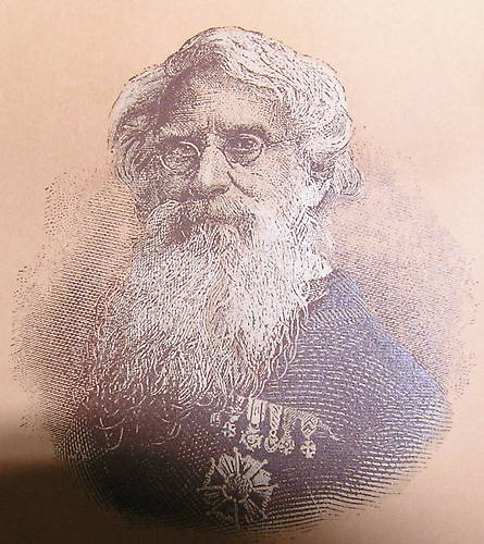
This experience has tweeked my interest in possibly designing a small one tube, single-band, low power ham radio transmitter using a 6FD7, 6EM7 or 6GF7A. Such a simple circuit would be used for CW (Continuous Wave) operation, using Morse Code. I'm sure that this reknown gentleman would approve!

Image

Oh, yeah, I also got the Fender "Deluxe" Clone tested and working tonight. I put it together, back in the early summer, and finally rounded up all the necessary tubeage (5Y3GT, 2 6V6GTs, 12AX7 and 12AY7) out of the tube stash. next step is to get one of the ready-built cabs from triode, as my woodworking skills are totally lacking, and I want to make this thing look reasonably good...

/ed B
Real Radios Glow in the Dark
User avatar
EWBrown
Insulator & Iron Magnate
 
Posts: 6389
Joined: Wed Mar 19, 2003 6:03 am
Location: Now located in Clay County, NC !

Re: 6FD7 radio transmitter?

Postby Geek » Sun Sep 05, 2010 11:55 pm

EWBrown wrote:This experience has tweeked my interest in possibly designing a small one tube, single-band, low power ham radio transmitter using a 6FD7, 6EM7 or 6GF7A. Such a simple circuit would be used for CW (Continuous Wave) operation, using Morse Code.


I often thought of a "spud" TX with one of those. Because of the lack of shielding between the sections though, I think the power triode may need to be grounded grid?

Cheers!
-= Gregg =-
Fine wine comes in glass bottles, not plastic sacks. Therefore the finer electrons are also found in glass bottles.
User avatar
Geek
KT88
 
Posts: 3585
Joined: Sun Oct 21, 2007 3:01 am
Location: Chilliwack, British Columbia

Postby Quad » Mon Sep 06, 2010 12:46 am

Ed, thanks for posting the info on these spud amps,
and especially the Antek PT find. Someday (if/when I
find a cheap OPT pair), I hope to build a
stereo amp with the pair of 6EM7s I have gathering dust
at the moment.
Quad
KT88
 
Posts: 254
Joined: Mon Jan 14, 2008 6:54 am
Location: India

Postby soundbrigade » Mon Sep 06, 2010 11:23 am

Someone else but me seems to likes Compactron tubes. Nice work Mr Brown. ;)
Magnus

"It is always more difficult to fight against faith than against knowledge."
User avatar
soundbrigade
KT88
 
Posts: 1760
Joined: Mon Jan 28, 2008 4:57 am
Location: Little Paris, Sweden

Postby EWBrown » Mon Sep 06, 2010 6:33 pm

Another potentially useful triode-pentode combination is the 6MF8 compactron. Same "12DZ" pinout as the 6LU8, just a different power pentode, which is very similar to a 6EZ5, which in turn is similar to 6V6GT.

The 6JZ8 is another "12DZ" triode-pentode combination, not quite as useful for audio purposes, due to having a lower-mu triode and somewhat "wimpy" pentode, but it has been used successfully in a very simple tube regulated PSU

I was experimenting with a simple 6JZ8 regulated PSU design from GE's tube manual, and decided to try a 6MF8 in the place of the 6JZ8, and I found that I got better results; improved stability and a higher current capacity.

The 6JZ8 started drooping before i could achieve 50 mA, and at that point its 7 Watt plate dissipation rating was already being exceeded. The 6MF8 has a PD of 12 W and appears that it can safely go well beyond that.

I started getting voltage "droop" around 75 mA, but then I was exceeding the choke's 65 mA curent rating, and the power trannie was right at its limit.

The 6LU8 should also work very well in this circuit, though I haven't yet tried it.

/ed B in NC
Real Radios Glow in the Dark
User avatar
EWBrown
Insulator & Iron Magnate
 
Posts: 6389
Joined: Wed Mar 19, 2003 6:03 am
Location: Now located in Clay County, NC !

Postby EWBrown » Wed Jul 11, 2012 12:54 pm

Found this through bottlehead Forum, discussion of selecting the proper inductance and capacitance values for parafeed output circuits. Pretty well "demystifies" this technique, and is a lot better than my SWAG calculations.

http://www.siteswithstyle.com/VoltSecon ... d_fun.html

/ed B
Real Radios Glow in the Dark
User avatar
EWBrown
Insulator & Iron Magnate
 
Posts: 6389
Joined: Wed Mar 19, 2003 6:03 am
Location: Now located in Clay County, NC !

Previous

Return to diy hifi

Who is online

Users browsing this forum: No registered users and 6 guests