new 6V6 amp

the thermionic watercooler

new 6V6 amp

Postby sorenj07 » Mon Sep 10, 2007 9:39 pm

considering the following implementation. Power shouldn't be amazingly over 10W but sound could hopefully be good. I went with the 6N7S as the LTP driver simply because it's somewhat similar to the 6N1P in gain but in a nice octal bottle.

Any thoughts? Think it'll work?

Image

I'm thinking that I'll use a 400-0-400V 200mA PT with various chokes in the power supply. Hopefully the input cap won't have to be quite so big in order to get the B+ of around 400-410V.
User avatar
sorenj07
KT88
 
Posts: 925
Joined: Tue May 02, 2006 2:39 pm
Location: Berlin

Flash Tubes

Postby EWBrown » Tue Sep 11, 2007 5:40 am

410VDC is way too high for 6V6s, IIRC, the max voltage is around 315VDC. Typically they should be around 250-285VDC, and 300Vis about as high as one should apply to this tube.... Of course with this safer B+ value, the grid biasing voltage may have to change to a less negative value.

http://www.mif.pg.gda.pl/homepages/fran ... /6V6GT.pdf

FWIW, 6AQ5s and their 5V and 12V derivitaves are nearly identical to 6V6s (and 5V6s and 12V6s), and 12AB5s are very similar operating characteristics , but with a 12 V filament and a 6973 pinout.

If you want 6 mA on the phase splitter, the "set resistor" would be in the range of 11-12 ohms (both are common 1/4 watt values).

Given that the two halves of the 6N7S are reasonably well matched, that would be 3 mA per side, so the 33K resistor would drop approximately 99 V (OK, I'll call it 100V). Best performance wound be if the 6N7S plates are around half of the B+, so in this case, with 400V, then the resistors should be around 66.7K (68K is more than close enough, at 3 mA per side, that is a 204VDC drop across the resistor). If you drop the PI's B+ to 300VDC, then 47-51K should do the job. (approx 150VDC across the plate resistors).

In addition, I'd directly ground the "lower" 6N7S grid, rather than use the 1K resistor.

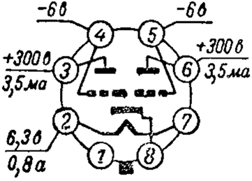
I haven't found any detaied data on the 6N7S (6H7C) except for this on a Russian site:

Image

300V @ 3.5 mA on the plates, -6V on the grids, 6.3V @ 800 mA for the filament.

UPDATE!!!!

http://frank.pocnet.net/sheets/113/6/6N7S.pdf

This is Frank Phillipse's tube site, same data (and a lot more) as can be found by going through TDSL. I've not had any problems with this site, thoughit can be a bit slow sometimes. Of course, around here, we have so many firewalls and other electronic "prophylactics" on the network, so that almost nothing can get through... However,

I have found that Adobe Rader 8.* sometimes goes into this "I want to update myself" mode, I just "cancel" out and nothing reallyhappens. If you click "continue" it goes into a "circular argument," much like a snake trying to swallow :o Yellow_Light_Colorz_PDT_09 its own tail...


/ed B in NH
Last edited by EWBrown on Thu Sep 13, 2007 11:53 am, edited 2 times in total.
User avatar
EWBrown
Insulator & Iron Magnate
 
Posts: 6389
Joined: Wed Mar 19, 2003 6:03 am
Location: Now located in Clay County, NC !

Postby erichayes » Tue Sep 11, 2007 1:38 pm

Don't know about the rest of y'all, but that update link was a fatal one for me. Be prepared to reboot.

Soren, what Ed said (he beat me to it). FWIW, 'AQ5s are only good for 250V; otherwise they're 'V6s. Also, my preference is to use a really high grade .22-.47µF cap to ground the AC component on the grid. Fender used resistors or RC networks to alter the midrange frequencies in their amps that used LTPIs, but if you're looking for accuracy, let that grid go straight to ground.
Eric in the Jefferson State
erichayes
KT88
 
Posts: 987
Joined: Fri Jan 23, 2004 9:01 pm
Location: McKinleyville CA

Postby sorenj07 » Tue Sep 11, 2007 6:47 pm

ok, generally people in most places corrected the pretty boneheaded mistake I made about tube dissipation. I'm shooting now for around 300V, 40mA for 12W of dissipation. I've got two 6Ay3 damper diodes to use as rectifiers. I'm looking at using the Dynaclone PA060-S PT which puts out a beefy 300mA of 360V and has a separate 6.3V winding that would be perfect for these damper diodes. I might well also use 5V6's since there's a 5V 4A winding on there too. I like the looks of this transformer.

one other thing: I'd like to have a pretty advanced autobias setup for the finals. does anyone know how i might be able to implement something from this website?

http://www.tubecad.com/2005/May/blog0046.htm

I was thinking about the bottom schematic but was kind of confused about the unlisted part values, as well as using it with a B+ of 300 or so volts.

I've been warned multiple times about using the LM334 without a negative voltage supply, but how could I implement one? Would voltage doubling off one of the 6.3V windings and filtering with a CRC be all right? you just connect the "in" leg of the LM334 to the negative supply instead of ground, right? how do you calculate the current adjust resistor? I'd like 6mA between each LTP...
User avatar
sorenj07
KT88
 
Posts: 925
Joined: Tue May 02, 2006 2:39 pm
Location: Berlin

Postby EWBrown » Wed Sep 12, 2007 6:20 am

The tube curves do show higher plate voltages beyond the safe maximum, those are generated by the action of the output transformer, the inductive EMF wil generate extra positive and negative voltage swings around the B+ voltage, without that action, the trannie would just be an oversized and expensive power resistor...


One approach that I've used for "autobias" is to replace the each tube's cathode resistor with an LM317, the input connects to cathode, the output is connected to the "adjust" with a resistor to set the bias (R = 1250 / I (mA) ). The Adjust pin is then grounded. Bypass the cathode in the normal method, 220 to 470 uF, to the ground bus.

Another approach is to use an LM7805, input to cathode (and bypass cap), output feeds into a load resistor which will in turn set the current (125 ohms for 40 mA), and the center ground pin and "tab" can be grounded.
In order to prevent any nefarious ground loops,the device should still be insulated from the chassis, if heatsinking is needed - it usually is not, as the actual power dissipationthrough the LM7805 is in the order of 500-600 milliwatts.

This has been discussed in other yopics on this forum. For 40 mA, the resistance would work out to 31.25 ohms (two 62 ohm, 1/4 W in parallel is more than close enough). and, for 35 mA, 36 ohms does the job.

The only caveat is make sure that you do not exceed the device's input voltage rating, with 6V6s, and EL84s this is not a problem as the voltage will "set" around 12-16VDC, depending on the tubes used.

Now, having said all that, this auto-biasing works best when the tubes are in class A operation, it gets a bit "sketchy" in ABx operation. Just keepthe cathode current around 40 mA and you should be OK.

I've used the LM334 with the 6EM7 PP amp, and it sets the VA/PI cathodes about 2.2VDC above ground. THis is kinda cutting it close to the bone, but it still works just fine. In this case a small negative voltage reerence would not hurt, though I've not found it necessary.

With the 6N7S (or US NOS 6N7 / 6N7GT) the cathodes DC voltage will sit somethat higher (around 6 to 8 VDC,) at 3 to 3.5 mA per section, so a negative rail shouldn't be needed. The lower-gain 12AU7 / 61689s cathodes usually sit around 13 VDC above ground at 3 to 3.5 mA per section.

If you want or need a negative rail, the best approach is to use a small 6 to 12 VAC CT trannie to generate the negative voltage, ( or ypu can disembowel a wall wart and use its trannie and DC components) the current requirement is very low. This will avoid setting up any unexpected and unwanted weird feedback paths. The DC voltage would be rectified iand filtered as required, and adding a LM series voltage regulator might be a good idea.

Now, if you want to keep the tubes in an "all Russian" theme, the 6P3S is somewhere in operating characteristics between a 6V6GT and a 6L6G. (Not the full house power of a 6L6GC or 5881) These are usually available cheap from the same folks who sell the 6N7S. The only circuit variation would be the operating bias point, and the autobiasing circuitry automatically takes care of that. Makes 6V6 / 6P3S tube swapping a simple "plug 'n' pray" operation Yellow_Light_Colorz_PDT_02

HTH

/ed B in NH
Last edited by EWBrown on Fri Jan 30, 2009 8:32 am, edited 2 times in total.
Real Radios Glow in the Dark
User avatar
EWBrown
Insulator & Iron Magnate
 
Posts: 6389
Joined: Wed Mar 19, 2003 6:03 am
Location: Now located in Clay County, NC !

Postby sorenj07 » Wed Sep 12, 2007 8:23 am

Thanks for the biasing info. The hassle and danger of flipping over my monoblocks while they're on and using a MM and screwdriver to bias them is getting kind of tiring, assuming I have the equipment to do it (no MM in my dorm room... yet).

Anyway, I still have some questions. Here's what I assume to be the case: an LM7805 holds each tube's current constant, whereas a current mirror (as seen in my link, I think) holds the tubes in class A by keeping the sum total between output tubes total, but letting them swing along a regular, sloped loadline? At this moment I'm not sure which to choose.

The complexity of the setup doesn't really bother me as I plan on just etching some nice little PCB's. No more crazy, precarious mid-air soldering stunts. I want this thing to look professional.

Anyway, the 6p3s option sounds great! The nice thing is, whenever I feel like juggling a couple of transformer secondaries, I can still use 5V tubes. Maybe I could even use a switch or something. I've actually never used american NOS.. Anyway what is y'all's opinion on the 6P6S? It's supposedly a 6V6 equivalent but I've read some harsh things about them.. consequently, they seem to be rather cheap on the Bay.
User avatar
sorenj07
KT88
 
Posts: 925
Joined: Tue May 02, 2006 2:39 pm
Location: Berlin

Postby EWBrown » Wed Sep 12, 2007 8:50 am

I haven't used the 6P6S, so I can offer no comment as to their good and bad points. Probably just like the lower priced 6P14Ps, the operating characteristis can have rather wide "lattitude"... :o

Re the auto bias, I like to keep things simple, though the "crossed garter" approach may work for 6V6s with appropriate R value changes.

Either the LM317 or 7805 version works fine, just choose from whatever you have on hand or can find locally.

FWIW, the ST35 "blue board" rev D has pads and accomodation for the LM317 current regulator biasing, but I am not sure if the documentation fully describes how to implement it. (I haven't checked over there recently).

5V6 and 12V6 are fine, and NOS usually go for cheap...


/ed B in NH
Real Radios Glow in the Dark
User avatar
EWBrown
Insulator & Iron Magnate
 
Posts: 6389
Joined: Wed Mar 19, 2003 6:03 am
Location: Now located in Clay County, NC !

Postby sorenj07 » Wed Sep 12, 2007 12:56 pm

EWBrown wrote:If you want or need a negative rail, the best approach is to use a small 6 to 12 VAC CT trannie to generate the negative voltage, ( or ypu can disembowel a wall wart and use its trannie and DC components) the current requirement is very low. This will avoid setting up any unexpected and unwanted weird feedback paths. The DC voltage would be rectified iand filtered as required, and adding a LM series voltage regulator might be a good idea.

is there a reason that the transformer has to be CT? Also, is it still possible to have such weird feedback if I tap off the 6.3V that feeds the damper diode rectifiers, as opposed to the 6N7S'?
User avatar
sorenj07
KT88
 
Posts: 925
Joined: Tue May 02, 2006 2:39 pm
Location: Berlin

Postby EWBrown » Thu Sep 13, 2007 5:22 am

Once again, I read "6N7S" but saw 6SN7: (I shouldn't write these posts so early in the AM)

With the 6N7S (or US NOS 6N7 / 6N7GT) the cathodes DC voltage will sit somethat higher (around 6 to 8 VDC,) at 3 to 3.5 mA per section, so a negative rail shouldn't be needed. The lower-gain 12AU7 / 61689s cathodes usually sit around 13 VDC above ground at 3 to 3.5 mA per section.


6SN7 cathodes will sit around 6 to 8 VDC above ground with the LM334 set to 6 mA. On the other hand, after looking at the curves on the Russian 6N7S (6H7C) data sheet, it looks like the cathodes would be closer to 1.8VDC @ 3 mA per section, with a B+ of 300VDC, and a plate voltage of 150VDC. So, it would be a good idea to reference the negative side of the LM334 to around -5 to -6VDC.

The 6V winding that feeds the damper diodes filaments is going to be in pretty close proximity to some fairly high voltage, so it probably wouldn't be too good to use that particulat winding to generate the -6VDC rail.

The 6H7C and 6V6 filament winding would be a better choice. My Thoughts about the "weird feedback path" are probably unwarranted,
it should be OK to derive the negative reference voltage from that winding.

In my next post, I'll describe an interesting and very simple "self-balancing" phase splitter circuit from the 1949 ARRL Amateur Radio Handbook. This may be a good alternative chice for your application

The two different PP modulator cuircuits shown, one used a 6N7 and the other used a 6SL7 for the PI stage. One drove a pair of 2A3s, the other drove 6B4Gs, but these should work fine with 6V6s or 6P3Ss as well.

This will not be too much of a departure from your circuit, just no LM334 (they didn't exist 58 years ago) and the second (lower) PI grid takes its signal from the junction between the 6V6 grid resistors (this will necessitate a cathode-biased power section).

/ed B in NH
Real Radios Glow in the Dark
User avatar
EWBrown
Insulator & Iron Magnate
 
Posts: 6389
Joined: Wed Mar 19, 2003 6:03 am
Location: Now located in Clay County, NC !

Postby EWBrown » Thu Sep 13, 2007 6:07 am

(This will be a work in progress, so please be patient, as I'll be doing some in-process editing) Yellow_Light_Colorz_PDT_02


Image

Starting with your circuit, first remove the LM334 and its current setting resistor, and replace it with a 1500 ohm, 1 watt resistor between the joined cathodes and ground, and "lift" the grounded end of the lower grid's 1K resistor. This will be used a little bit further on...

The two 0.47 uF coupling caps can be reduced to 0.1 or 0.22 uF, with no audible effect onthe low freq response.

The 1.5K rcathode resistor may be capacitor bypassed, as the audio signal isn't transferred to the lower PI section through the cathode, but rather, through its grid.

Given a B+ voltage of approximately 300VDC, (perhaps 280 VDC would be better), the two 6N7S plate resistors should be 100K, 1W. If a 6SL7 is used, these plate resistors should be 220K, 1/2 W. These values were derived from the "resistance coupled amplifier" data in the Handbook.
(The reason for choosing 6SL7 willbe explained further on, as well).

(I know, this may be getting a bit condfusing, I'll have to scan or photograph the actual schematic and post it here)

The 6V6s have to be cathode biased, the joined cathodes connect to a 240 to 270 ohm, 5 watt resistor, bypassed with a 220 to 470uf , 35V cap, to ground.

For 40 mA current, use 240-250 ohms, for 35 mA use 270 ohms. These could be independent cathode resistors and caps, just double the resistor value for each separate resistor. An LM317 or 7805 CCS could be used, but then this isn't really 1949 "old school" design philosophy) Yellow_Light_Colorz_PDT_03

Since the 6V6 section will be cathode biased, the two G1 grid resistors should be 220K, 1/2 W. Now, instead of connecting their "center" junction to ground directly (as is the usual case), connect the junction to a third 220K 1/2 W resistor, then connect this third resistor's other end to ground. Connect the junction of the three 220K resistors back to the "lower" PI grid, through the already existing 1K grid stopper resistor.

The operation of this circuit is a bit tricky to describe, I'll attempt ito do so in a subsequent posting.

The plate and UL connections to the OPT can remain as-is, the 470 ohm resistors can be 1 watt, 3W isn't really needed.

The 6V6s should see about 305VDC at the plates and SGs, so their B+ should be 310-315VDC, depending on the DCR of the OPT primary.
This is derived from the "normal" operating at 285VDC on the plates and SGs, with a fixed bias of -19V. Since the cathode bias raises the cathode voltage from 0V to +19V, just raise the 285VDC accordingly. This was given in the data sheets, with 70 mA total for the pair, 35 mA for each tube.

There should be some CRC or CLC isolation between the PI stage's B+ and the 6V6s' B+, that is why I suggested using 280 to 300 VDC for the PI's B+, the dropping series resistor value can be calculated, but I'd SWAG around 10K ohms for 30V drop, and 6.8K for 20V drop. (Assuming about 3 mA for the PI section B+)

The 6SL7 current will be lower, probably around 1.2 mA for the PI pair so the resistor should be accordingly higher.


The 6SL7 has an inherent advantage, with womewhat more gain, but it's chief advantage is that it is also available with a 12V filament, as are the 6V6 / 6V6GTs. The 12V versions are lower cost for NOS, and have the second advantage of having half the current consumption, 600 mA total for two 12V6s and one 12SL7, per channel. The 12VDC can be voltage doubled from the 6.3 VAC winding, or a 12.6VAC trannie could be used -
AC fis OK for the filaments, it doesn't have to be DC.

There is no 12V version of the 6N7 or 6N7S, as far as I know...

(to be continued...)

/ed B in NH
Real Radios Glow in the Dark
User avatar
EWBrown
Insulator & Iron Magnate
 
Posts: 6389
Joined: Wed Mar 19, 2003 6:03 am
Location: Now located in Clay County, NC !

Postby sorenj07 » Thu Sep 13, 2007 8:27 am

I'll try to wrap my head around the circuit you described later. For now, just know that I have two matched-section 6SL7's as well as my four unmatched 6N7S' so I can experiment with both. I'd rather use 6V6's for the output because 5V6's can also be used, powered from a standard rectifier-style 5V 3A secondary. I'm thinking a separate 6.3V 5A transformer for the damper diodes. Could I tap a negative supply from this damper diode supply without having the risk of weird feedback?

p.s. thanks for taking all the time to explain this to me, it's a lot better than trying to read a textbook. maybe that's obvious?
User avatar
sorenj07
KT88
 
Posts: 925
Joined: Tue May 02, 2006 2:39 pm
Location: Berlin

Postby EWBrown » Thu Sep 13, 2007 9:10 am

I'd still avoid using the damper diode filament winding for generating the negative 5V 6V DC for the LM334. The DD filament trannie has a lot of AC and DC high voltage very close (inside the damper tubes) and the risk of impressing an AC hum onto the PI circuitry is present.

The PI and 6V6 filament supply should be OK, try a simple half-wave doubler, off one side of the 6.3VAC, referenced to the CT ora resistive divider across that winding. The actual current needed is only around 12mA, so this should be pretty easy to do.

Minus 5V works out nicely, as it can be regulated with one of the small sized LM7905s or similar. Two 1N4007s, two 100-220 uF, 25VDC caps and a 7905 is all it would take.

The "self balancing" circuit was used a lot around 50-60 years ago, and with today's 5% and 1% resistors, should work quite nicely. If you can get ahold of one of the octal "relay sockets" then it would be easy to breadboard and try out the PI circuit, and simple bench supply could power it. The other commonly used PI of the day was a version of the "cathodyne", similar to that used in the Dynaco ST35. The Schmidt
and LTP designs wer not yet in common usage, or they were still in the developmental stages.The other "old school" PI alternative of the day was the interstage transformer. Not a good choice, today, the good ones are quite expensive...

Back in 1949, 20% and 10% tolerance components were the norm for DIY, and 5% was considered as precision (and accordingly priced) and 1% tolerance was expensive, and used in engineering and calibration labs, where they had the $$$ to spend.

I've been hunting around the 'net in order to find an existing schematic, that saves the process of trying to post my own schematic here Yellow_Light_Colorz_PDT_09 Yellow_Light_Colorz_PDT_05

I've not yet tried entering a 6N7 into Tubecad and see what it comes up with, that wouldn't be very "1949" Yellow_Light_Colorz_PDT_06 Yellow_Light_Colorz_PDT_03

/ed B in NH
Real Radios Glow in the Dark
User avatar
EWBrown
Insulator & Iron Magnate
 
Posts: 6389
Joined: Wed Mar 19, 2003 6:03 am
Location: Now located in Clay County, NC !

Postby EWBrown » Thu Sep 13, 2007 1:00 pm

Running a bit of TubeCAD on this "self balancing" PI circuit, I had to treat it as two "grounded cathode" circuits sharing a common cathode resistor, in order to get as close as TubeCAD allows for this one... This is in conformity with the circuit operation description given in the 1949 ARRL Handbook.

6N7 (and 6N7S / 6H7C):

300V B+, RA = 100K, RK = 3K (twice the PI's given Rk value), IP = 1.33 mA per triode, VP = 167V, Vg = -3.96V, gain = 27.56

6SL7:

300V B+, RA = 220K, RK = 3K (twice the PI's given Rk value), IP = 0.61 mA per triode, VP = 166V, Vg = -1.79V, gain = 53.85


With 0.1 uF coupling caps, either tube type's F-3dB low is 3.5 Hz, and F-3dB max is over 1 MHz. The two coupling caps could be reduced to 0.056 to 0.068 uF with no audible LF reduction.

Note:
The 6N7 is intended as a class B PP power triode, and can deliver 10 watts into a 10K P-P OPT, with 17.5 mA idle current and zero grid voltage.
Class B will have significantly higher distortion figures than Class A or AB1.

As a Class A1 driver, ithe 6N7 intended to have both sections in parallel, 294VDC on the plate, -6V on the grids, 7 mA (both sections), the RP is 11K and the GM is 3.2 mA/V and the mu is 35. (In a paralleled triode, the RP is halved, the gm is doubled, and the mu remains the same).


HTH

/ed B in NH
Real Radios Glow in the Dark
User avatar
EWBrown
Insulator & Iron Magnate
 
Posts: 6389
Joined: Wed Mar 19, 2003 6:03 am
Location: Now located in Clay County, NC !

Postby sorenj07 » Sat Sep 15, 2007 12:29 pm

Thanks so much for all these calculations! The thing is, though, will those numbers only work for a traditional phase splitter and not a CCS?
User avatar
sorenj07
KT88
 
Posts: 925
Joined: Tue May 02, 2006 2:39 pm
Location: Berlin

Postby EWBrown » Mon Sep 17, 2007 5:48 am

These tubes were dsigned decades before the idea of using CCS was ever conceived... The numbers reflact the "traditional" approach, but there is no reason that CCS wouldn't work - just make sure that the two tro\iode sections have reasonably close characteristics...

If you can get ahold of a variable regulated power supply like the Heathkit IP-17 or IP-32 (400VDC / 100 mA, plus filament and adjuatable bias supply) and some octal relay sockets, then "breadboarding" new circuit ideas then becomes very easy. I've seen these variable regulated tube supplies at hamfests for $25 and even less, the octal sockets for a buck or less. Other style tube sockets can be wired to terminal "barrier strips" for easy no-solder breadboarding.

When it comes to tube designs, I never say "never" when it comes to a new idea, I've been amazed at what works in spite of the hide-bound naysayers. :o

The 1626 was intended only as a class C oscillator and low-power class C RF amp, but it works and sounds very nice in an SET design

I've got a few WWII vintage RK34 / 2C34s (two triodes sharing the same bottle, with plate caps) which should work very well for low power SET or PP class A, even though they are also considered as "Class C" RF tubes.

/ed B in NH
Real Radios Glow in the Dark
User avatar
EWBrown
Insulator & Iron Magnate
 
Posts: 6389
Joined: Wed Mar 19, 2003 6:03 am
Location: Now located in Clay County, NC !

Next

Return to diy hifi

Who is online

Users browsing this forum: No registered users and 56 guests