Problem with 6L6 Monoblock

the thermionic watercooler

Problem with 6L6 Monoblock

Postby sorenj07 » Fri Aug 10, 2007 11:03 pm

I finally finished one of my 6L6 monoblocks. Aluminum was tough to polish, but at last I was able to wire the things. The other one is still sitting on the bench, not quite done.

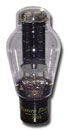
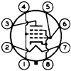
First, some photos. Then, the bad news :)

Image Image Image Image Image


Here's my problem. The amp started up fine, fed by a discman into a decent speaker. Upon playing the music, though, this horrible distorted bass rumble started blaring. I shut down the amp and it "killed" the home-theater voltage regulator thing it was plugged into, resetting the TV, cable box, etc. Surprisingly, the fuse didn't blow.

The amp, ignoring the noise (which I suspect is motorboating), sounded pretty good otherwise. The cymbal hits on Miles Davis' Nefertiti album came through pretty decently.

Back at my bench, I put on some gloves, tipped the amp onto its side, and measured some voltages. Or tried to. Voltage on the first motor run cap, the 100uF main B+ reservoir, started at 450V and rapidly rose to above my crappy tester's 500V limit. I then stupidly blew up said DVM when I put the leads from one side of B+ AC to the otherwords, probably around 1000V. Damn.

I'd had the bias pots at around half way. Without being able to measure tube current, I turned the 20-turn 25K trimpots a few times in one direction, then a few times in another, without getting much difference in sound.

One last thing. Turning the amp on and off back in my workshop didn't blow any fuses. I left the CD player off, but still plugged in, and turned on the amp. It was quiet, just the faintest bit of hiss and B+ ripple noise. I tapped the side of the chassis firmly (as it was vertical). The rumbling hum noise started up again, building pretty quickly to a steady loudness. What the hell? I made sure that not too much stuff was dangling around, even super-gluing a stiff piece of wire to the top capacitor to keep it from vibrating.


My questions - if it is motorboating, is there anything I can do? I made sure not to mess up the wiring of the OPT, but those long runs of DC between those last 22.5uF motor run caps and the input stages might be a problem. My main issue though is that I've never had this problem of crazy noise, and don't know what could be causing it. Someone suggested that tapping the bias voltage off the B+ could lead to a feedback loop, could this be it?
User avatar
sorenj07
KT88
 
Posts: 925
Joined: Tue May 02, 2006 2:39 pm
Location: Berlin

Postby Shannon Parks » Sat Aug 11, 2007 6:54 am

Hi Soren,

Your build looks real nice. Keep up the good work. The debugging stuff is just part of the hobby. Once the gremlins get rounded up, the pride in your work just goes up exponentially.

1) Get a new DMM. Hey, we've all blown up test gear. I burned up a real nice $1000 Agilent 30dB attenuator at work once. It was rated for 50W, and I hooked it up to a oddball satellite power amp which put out 100W. 'Course I realized my mistake immediately to add insult to injury. But there are those who have, and those who will. I still miss that attenuator, though. Yellow_Light_Colorz_PDT_13

2) Take all those voltages with no input and share them, please. Let's verify that all the stages are biased correctly. FWIW, the schematic looks OK to me. If everything is built per the schematic, I think you should be motorboat free. Plus you have no feedback, right?

A motorboating will sound just like that - a motorboat. :) Did it sound like that? Put-put-put-put-put.....
Last edited by Shannon Parks on Sun Aug 12, 2007 7:02 am, edited 1 time in total.
User avatar
Shannon Parks
Site Admin
 
Posts: 3764
Joined: Tue Mar 18, 2003 5:40 pm
Location: Poulsbo, Washington

Postby sorenj07 » Sat Aug 11, 2007 4:12 pm

Thanks! It's just too bad because my lucky streak of amps working right off the bat seems to have come to a close, that and the volume pot of all things blowing in that 6EM7 amp that I built... weird. I think I smoked the 10-ohm resistor linking signal to ground in that one too, and shocked my right hand between the AC fuse holder and ground when I tried to remove it. Rough stuff.

Anyway, back to the subject. What kind of DMM would you/anybody recommend? My budget is around $80 to completely clean out my debit account :( which I'd rather not do, but I can wait a bit to save. Are there new ones that are solid, or some vintage stuff that has a good reputation on ebay or something?

Did another experiment in the downtime. My friend has a DMM that I might want to borrow since I have to repair said 6EM7 amp of his. I wrapped a wire around input and ground (too lazy to grab a shorting plug from a couple floors above) and then turned on the amp. Result: A bit of hum or ripple or whatever, from what I suspect is a sketchy ground wiring job, but still relatively quiet. This continues for a while. I smack the chassis with my hand again, and the louder more weird-sounding humming starts up. It sounds too smooth to be what motorboating is, but it's really annoying and kind of a bummer. Shutting it off and turning it back on yields the same result - relatively quiet till I tap the chassis.

A couple questions. Should I try bypassing any of the resistors in the bias network with zener diodes to stop potential feedback loops through the PSU? I'm tempted to cut the wire linking signal ground to the secondary B+ cap (the 80uF one) and reconnect it from the main filter cap (the 100uF one) straight "up" to closer to the middle of the signal buss. Would this help hum? The trouble with all that pretty heavy-gauge copper wire is that it's a bitch to desolder/unwind it from stuff :(
User avatar
sorenj07
KT88
 
Posts: 925
Joined: Tue May 02, 2006 2:39 pm
Location: Berlin

Postby TomMcNally » Sat Aug 11, 2007 4:33 pm

I don't like the idea of the 10 ohm resistor ... ground is ground in a tube
amp as far as I'm concerned. I use a bus system of # 14 copper with
good results.

DMM's ... I bought a nice one for $ 160 and although it does cool stuff,
it has two display, can read freq and voltage at the same time, etc ...
OI like the el-cheapo eBay $ 12.95 ones I bought better. I got four of
them, and leave them at various places I'll need 'em. My eBay $ 12.95
clamp on current probe is nicer than the $ 400 one the electrcian has.

Motoboating is basically feedback - output getting to input somehow ...
are you using a feedback loop that is sketchy ? You'll find it.

... tom
User avatar
TomMcNally
Darling du Jour
 
Posts: 2729
Joined: Sat Nov 19, 2005 2:19 pm
Location: Northfield, NJ

Postby sorenj07 » Sat Aug 11, 2007 4:56 pm

OK, I'll hold off on the 10 ohm thing. I've only ever really seen it in old guitar amps anyway. As for feedback, the only possible ways that feedback could be getting through, AFAIK, are these: 1) the bias scheme - as the audio input loads the HT, it sags a bit, decreasing B+ and therefore raising current to the tubes even more. i suspect it isn't a huge issue since many ike's don't seem to have this problem and 2) mechanical issues involving used 6SN7's or maybe a 6L6WXT+ that I knocked over, or some other source of transduction inside like a cap or something. still kind of hard to understand how, but since tapping the chassis sets off this noise, you never know. 3) some grounding issue - how does my wiring look?
User avatar
sorenj07
KT88
 
Posts: 925
Joined: Tue May 02, 2006 2:39 pm
Location: Berlin

Postby erichayes » Sat Aug 11, 2007 7:14 pm

Hi Soren,

I have a sign on the wall, ironically, just above the fire extinguisher, that says "AN AMPLIFIER IS AN OSCILLATOR WAITING TO HAPPEN". I notice you don't have any inverse feedback applied, so that dictum is even more applicable.

Since the problem apparently occurs only when the amp is physically struck, the obvious first thing to check is the integrity of your wiring. One of my 1773s worked for three years before it started acting up--turns out I forgot to solder the !st audio cathode resistor on one channel.

Second thing is to eliminate the speaker/amp feedback loop. Get the speaker into another room or a closet and give the amp the whap test. If the problem is eliminated or diminished, you probably have a very microphonic 6SN7.

If the problem persists, at least the "Stupid Amplifier Tricks" have been dealt with and you know what's not causing it.
Eric in the Jefferson State
erichayes
KT88
 
Posts: 987
Joined: Fri Jan 23, 2004 9:01 pm
Location: McKinleyville CA

Postby TomMcNally » Sat Aug 11, 2007 7:17 pm

Your wiring job is nice and neat! My only comment would be this,
and it might have something to do with the hum. Typically, you don't
want to connect the third wire of the power connector to the ground
system, only to the chassis (with the short green tail like you have it)
Many people suggest that the only ground point of the buss should be
at the RCA input jack.
You have also have a solid connection from the low side of the output
transformer right over to the input jack. I normally use some small
22 gauge wire as a sample of the output for the feedback loop, and
don't ground the low side into the buss. You have the power supply
grounds as they should be ... typically you want the CT of the HV
transformer as close to the negative ends of the power supply caps
as possible.
User avatar
TomMcNally
Darling du Jour
 
Posts: 2729
Joined: Sat Nov 19, 2005 2:19 pm
Location: Northfield, NJ

Postby sorenj07 » Sun Aug 12, 2007 1:42 am

erichayes wrote:Since the problem apparently occurs only when the amp is physically struck, the obvious first thing to check is the integrity of your wiring . . . Second thing is to eliminate the speaker/amp feedback loop. Get the speaker into another room or a closet and give the amp the whap test. If the problem is eliminated or diminished, you probably have a very microphonic 6SN7.

If the problem persists, at least the "Stupid Amplifier Tricks" have been dealt with and you know what's not causing it.

Good advice and I'll definitely give it a go. The amp was indeed right next to each speaker I demo'ed it with. I've got some obscenely long pieces of Romex that I could snip at each end. Can't go wrong with that heavy-gauge stuff. Incidentally, all my nice copper ground busses are stripped Romex left over from our renovation.
User avatar
sorenj07
KT88
 
Posts: 925
Joined: Tue May 02, 2006 2:39 pm
Location: Berlin

Postby sorenj07 » Sun Aug 12, 2007 1:48 am

TomMcNally wrote:Your wiring job is nice and neat! My only comment would be this,
and it might have something to do with the hum. Typically, you don't
want to connect the third wire of the power connector to the ground
system, only to the chassis (with the short green tail like you have it)
Many people suggest that the only ground point of the buss should be
at the RCA input jack.
You have also have a solid connection from the low side of the output
transformer right over to the input jack. I normally use some small
22 gauge wire as a sample of the output for the feedback loop, and
don't ground the low side into the buss. You have the power supply
grounds as they should be ... typically you want the CT of the HV
transformer as close to the negative ends of the power supply caps
as possible.

the thing is, my RCA jacks are insulated from the chassis, so the only electrical connection to the amp's ground is at one of the IEC socket screws. I'd rather leave it connected for now because I don't think that much other than the 15-amp breaker in the next room would keep the city current out of my fingers.

However, I DO have the HV CT way to the right and not more to the left where the buss connects to the main reservoir cap, but since only the y-shaped choke bucking cap thing is between it and said cap, I'm guessing I'm OK?

anyway, one last thing. you mention not grounding com to the buss? where would you ground it then? is it kosher to leave the OPT secondaries floating?
User avatar
sorenj07
KT88
 
Posts: 925
Joined: Tue May 02, 2006 2:39 pm
Location: Berlin

Postby TomMcNally » Sun Aug 12, 2007 1:48 pm

You may be getting acoustic feedback as Eric suggested ...
experiment a little and see what happens.

Like I mentioned, most people don't like to connect the
third wire ground into the audio ground, just to the chassis.
The audio bus ground usually only grounds at the RCA jacks.

What I mean with the feedback ground is think of it as a
small sample, small guage wire taking it back to the
earlier stage, a hot lead and a ground lead.

Look at it this way ... an oscillator is a circuit where the
output feeds the input and it sustains itself. So in an
amplifier, it's good to keep outputs away from inputs.
When I see an amp with the RCA inputs right next to
the output jacks, I cringe ... audio can radiate and get
back in.

... tom
User avatar
TomMcNally
Darling du Jour
 
Posts: 2729
Joined: Sat Nov 19, 2005 2:19 pm
Location: Northfield, NJ

Postby sorenj07 » Sun Aug 12, 2007 8:42 pm

had a chat with Eric Hayes and during the course of it, cut the ground wire connecting signal ground from the RCA to the 80uF cap, and soldered a new ground wire connecting the main 100uF cap to a point on the signal ground buss between the 6SN7's and the 6L6s' 10-ohm cathode resistors. Hum problem gone, except for some quiet background stuff that doesn't bother me that much. I'm happy :)
User avatar
sorenj07
KT88
 
Posts: 925
Joined: Tue May 02, 2006 2:39 pm
Location: Berlin

Postby sorenj07 » Mon Aug 13, 2007 10:42 pm

Image Image Image

well, there they are. both work fine except for some substantial hum from the left one. bias is at 55mA each with a B+ of 500V. I don't exactly know what the bias voltage is, I just twiddled the pot until I got .55V across 10 ohms.

the amps seem extremely sensitive (they're a straight up williamson design). is there a way to skip a gainstage such as paralleling the first two 6SN7 sections to make one beefier phase splitter? I'm temped just to cut out the direct-coupled gainstage, because otherwise I have no volume control unless I build a unity-gain buffer driving a volume pot..
User avatar
sorenj07
KT88
 
Posts: 925
Joined: Tue May 02, 2006 2:39 pm
Location: Berlin

Postby TomMcNally » Tue Aug 14, 2007 8:32 am

Great job with the mirror image layout ! They look great.

... tom
User avatar
TomMcNally
Darling du Jour
 
Posts: 2729
Joined: Sat Nov 19, 2005 2:19 pm
Location: Northfield, NJ

Postby jduffy » Tue Aug 14, 2007 11:17 am

TomMcNally wrote:
Like I mentioned, most people don't like to connect the
third wire ground into the audio ground, just to the chassis.
The audio bus ground usually only grounds at the RCA jacks.


Point well taken.
User avatar
jduffy
 
Posts: 43
Joined: Sat Jan 06, 2007 2:52 pm
Location: SoCal

Postby sorenj07 » Tue Aug 14, 2007 3:35 pm

TomMcNally wrote:Great job with the mirror image layout ! They look great.

thanks! in the end it's a lot more real estate than I would have expected, but using those motor run caps demands sacrifices like that. Plus the weight per watt ratio might get some help if I pop some higher power tubes in there. The PT should put out a bit above 200mA into 500V, so maybe some KT88's or KT90's? The fact that I used an oversized 6.6K 60W OPT might also help..
User avatar
sorenj07
KT88
 
Posts: 925
Joined: Tue May 02, 2006 2:39 pm
Location: Berlin

Next

Return to diy hifi

Who is online

Users browsing this forum: No registered users and 7 guests