HOGHEAD wrote:Hi, yes I did add the jumpers from y to 5 and z to 4 but I am unsure of some of the readings, pins 1,2,and 3 read ok but pins 4 and 5 I get about 45k and 25k ohms and pin 6 I get 1k and pin 7 I get 50 omhs and finally on pin 8 I get 50 omhs. this is on V1-6LS7. All the other sockets and plugs seem to be ok. Jim
Hi Hoghead,
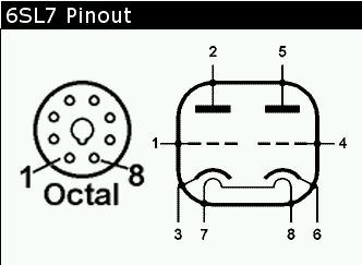
1 - high Z
2 - high Z
3 - high Z
4 - Should be around 480K, ie the resistance of the the grid stopper and grid resistor to ground. Probe around and double check those resistor values. I see I have 23K on my resistance sheet for the 12AX7 grid - this is an error. I apparently had my signal source loading the input. Yellow_Light_Colorz_PDT_05
5 - This should be at least 100K. Double check the resistor values here, too - particularly R5. On my meter it starts drifting higher as this is connected to the last filtering cap in parallel with the 470K load resistor.
6 - 1.1K - double check the value of R4
7 - 50 ohms
8 - 50 ohms
So take a closer look at 4, 5 & 6.
Shannon